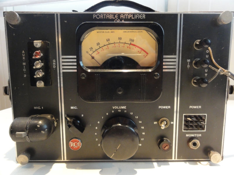
The RCA OP-6 ‘Portable Amplifier’ is one of a handful of truly visually-iconic vintage mic preamps. The OP-6 was designed as a “remote,” as-in, ‘on-location’ single-channel mic preamp for radio station broadcasts. It uses three 1620 (6J7) tubes – most mic pre designs of the period use two. Furthermore, the 1620s are in pentode operation rather than triode. The result: a ton of gain. 95db, apparently. This is almost twice as much gain as the classic RCA BA1 and BA2 mic pres. OP-6s are in high demand – click here for a seller asking $2900. Further indication: Blackbird Rentals in Nashville has thirteen in stock as rental units. The first time I heard an OP-6 in use was at Blackbird; I was producing/directing a live-in-the-studio performance for Martina McBride and John McBride was engineering; he was using the OP-6 for something… I can’t remember what exactly. Anyway, it caught my eye and we talked about it a bit; later I learned that he has an especially strong appreciation for these units. A strong endorsement coming from the man who likely owns more vintage pro audio gear than anyone who ever has or ever will live.
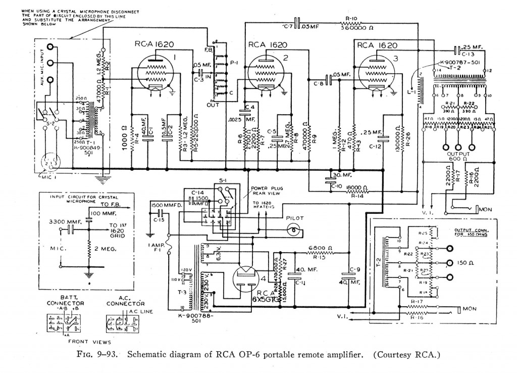 The OP-6 schematic is pictured above (this file is readily available in high-res on the internet). So anyhow, if we consider how in-demand the OP-6 is, it seems striking that no one offers a modern equivalent for sale, even on a small-scale level. If you take a close look at the circuit, the reasons become apparent. There are two big obstacles to re-creating even a semblance of an OP-6. First is the input attenuator:
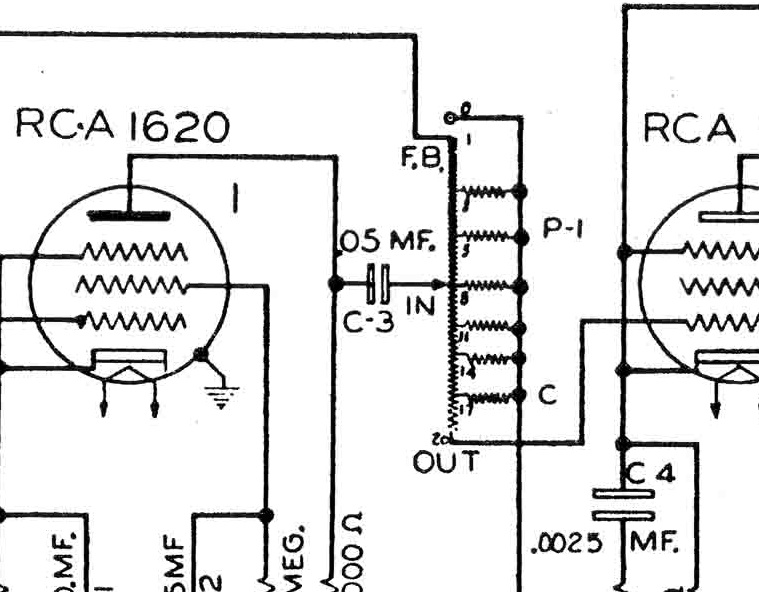 Sure, it’s a voltage divider; probably constant impedance; but what exactly are the values? And what about that value of that feedback path issuing from the attenuator back to the input stage? If I could get my hands on an original OP-6 and open up the attenuator, sure I could maybe sort it out. But I imagine that re-creating that part on custom order could cost hundreds of dollars; frankly I have no idea.
The second obstacle to re-creating the OP-6 is the output stage choke.
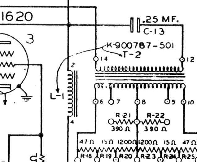 The choke is designated L-1 in the schematic. Curiously enough, it’s actually physically part of the output transformer. Based on this fact, there is zero chance that this was an off-the-shelf choke, say a UTC for example, that we could track down. OK – but the crucial value of a choke in a circuit like this is the inductance. So long as the voltage an current handling values are sufficient, any choke of same inductance should give a similar result. Now again, if I had an original OP-6, I could measure the inductance and maybe a current off-the-shelf part exists to satisfy the requirements. But… I don’t think anyone out there is gonna send me their prized OP-6 to open up. And $2900 is a pretty stiff R+D cost. So what do we do? Well, in the absence of any actual electrical engineering training, I looked for some good advice and then I guessed.
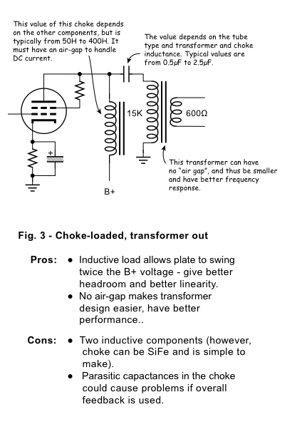 The very friendly+talented John Atwood sent me the diagram above; in response to what I can’t recall. This diagram explains why the choke is necessary in order to get the best possible performance from a single-ended vacuum tube line output stage. Looks pretty similar to our OP-6 output stage, right? Based on this… I made a wild guess. I ordered the very inexpensive Hammond 156C choke. 150mh inductance with 8ma current capacity. 8ma might be a little low, but I have found that Hammond really undersells the specs of their transformers, so I’m not worried.
Alright so now we’ve got a choke that might work. What about that input attenuator? The best course of action would probably be to get a used 100k Daven T-pad, but without implementing the feedback path that the stock OP-6 attenuator has, it seems like this is slightly pointless vis-a-vis maintaining originality. So instead: I used the input stage from my favorite, yes yet again, the RCA BA-2.
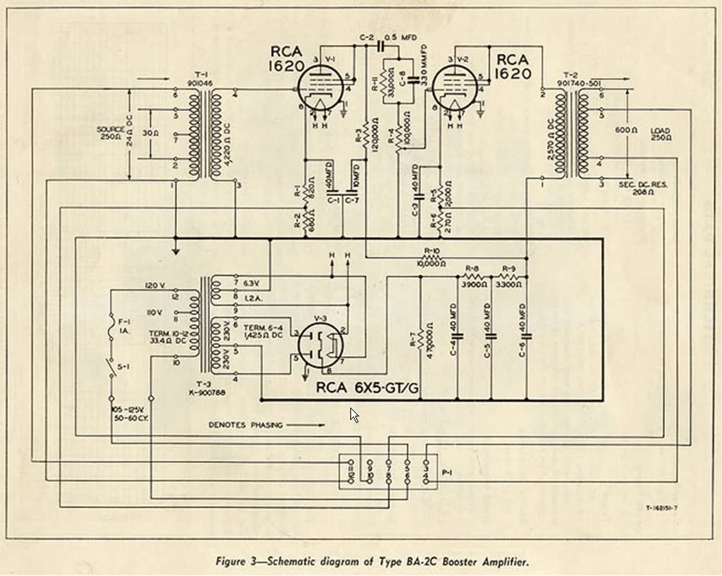 The BA-2 schematic is pictured above. The input stage uses a 1620 tube, wired as a triode, with a 100k ohm pot following it. So I just took this input stage, up to the pot output, and wired it in front of the second two OP-6 stages (starting at the grid of stage #2). When I did this, the whole system worked fine except when the volume pot was a zero (IE., when the grid of tube #2 is shorted to ground). This caused weird noise and a little humming. Not sure if this is due to the negative feedback in that stage, or if this is simply a general characteristic of 1620s when they are run in pentode – but it sounded awful. The easy solution? I added a 1M resistor from the grid to ground, and isolated this from the pot with a 1K grid-stopper resistor. Done and done. The BA2/OP6 Hybrid is born.
*************
********
***
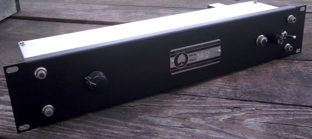
 The finished piece is shown above. I used a 6X5 rectifier tube like the OP-6 uses; in fact, with the exception of using DC filament voltage, I kept the power supply the same as the OP-6.
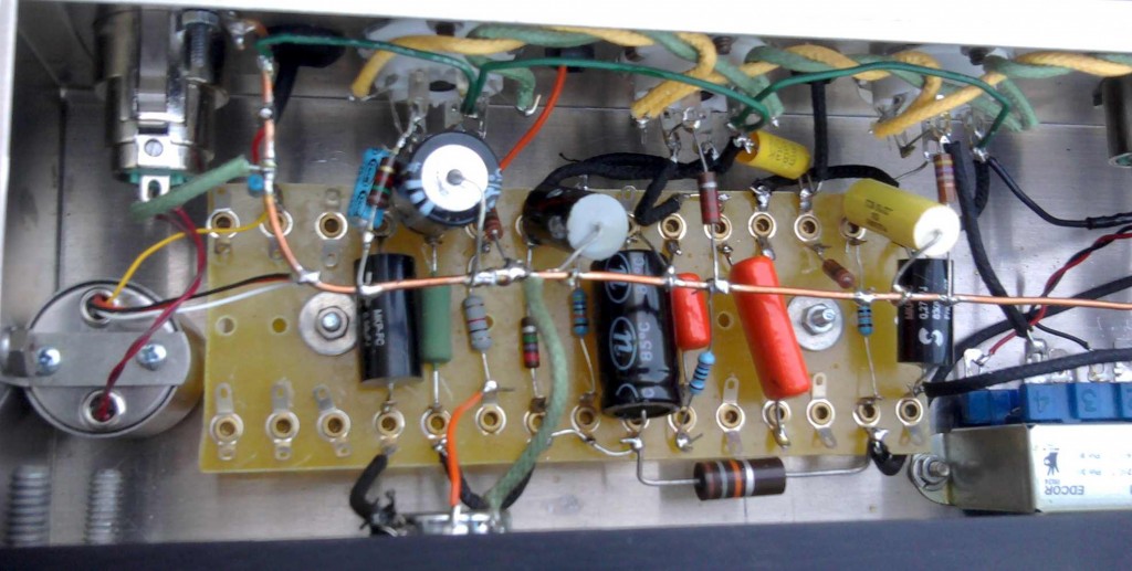 The audio portion of the circuit is shown above. What with the three pentode stages and feedback paths, this is extremely complicated for a mic preamp. A lot of parts. On the left you can see my usual Jensen 115 input transformer. Audio caps are a mix of Solen, sprague, and some random Russian ones. Basically whatever would fit. Resistors are random as well; now that I have confirmed that the piece works well, I will probably replace the carbon-comp resistors in the B+ chain with some quieter modern resistors. On the right is the output transformer. I used an edcor 15K: 600; $10.22!
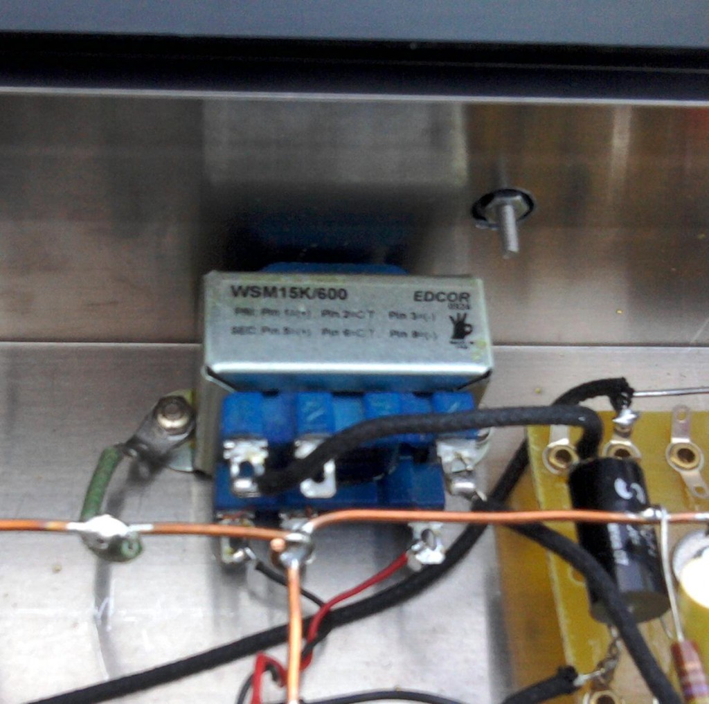 Even though this edcor is unshielded, there is zero hum following the volume pot. And as for performance? I did a frequency sweep through the entire unit; response is absolutely flat from 15hz to 10k hz. At 10k there is a rise of about 1db up to 22khz, at which point response begins to fall of pretty rapidly. This is really excellent performance considering the inexpensive transformers. I did not measure the gain but there is a lot of. The output level can get extremely hot.
Anyhow. That’s it for now. As soon as I have a minute I will provide some audio test examples; I’ll post some A/B examples of this unit versus an API 512, hopefully with both acoustic gtr and drums.
Thanks to DW at EMRR for helpful suggestions regarding this project.
***UPDATE*** Listening test has been done and results are posted here.
26 replies on “Building an (almost) RCA OP6 Mic Preamp”
Chris
Nice work!
I have worked on a few original OP6 preamps and I have done a little research into the value of the components in question.
Firstly the attenuator is made up of hand wound wire resistors built into something similar to a Daven attenuator but each one that I have tested has different values! My assumption is that the performance tolerances were very tight and values needed to be selected based upon the performance of the tubes used.
I considered building a step attenuator with similar characteristics(oh if I had the time).
The Telefunken V76 comes to mind when making comparisons, it also had selected components making tube replacement somewhat tricky if you don’t have proper test gear and the knowledge to use it.
The plate load inductor(again think Telefunken) had a DC resistance of around 10K if my memory is correct…next time I open one up I’ll research it a little further.
I kind of a fan of that EDCOR output transformer you used, performs nicely in the right circuit.
Nicely done.
Kevin Ink
Nice work! What power transformer did you use?
Thanks,
—
Don
Hi Don. Well it’s definitely a hammond – probably a 269EX, i imagine… this unit has been sold so I can’t say for certain. But generally i buy 269EXs for these sort of the things…. http://angela.com/hammondpowertransformer269ex.aspx
This edcor model is also a good choice… higher voltage but it will still work fine, might require a dropping resistor… http://www.edcorusa.com/products/729-xpwr128_120.aspx
Thanks, Chris! I’ve used that Hammond many times as well and it always works out fine. I have an order in at Edcor right now for some ribbon mic transformers so I might just call them and add the output transformer and power transformer needed for this project to my order. I’m definitely going to build one of these.
I just saw a glimpse of a closed-circuit feed for affiliates, of Brian Williams’ new NBC show. He was showing off the new set, and I believe there is an OP-6 on there (among the “antiques” displayed). He referred to it as a “Talent Meter”, but didn’t elaborate further.
Generally plate chokes for small signal work were much higher in inductance, as the clipping indicates, they went as high as 1 kH….that’s right, 1000 henries, although 50-100 was pretty common. They were used in building regenerative shortwave receivers more than in audio, because the choke was as expensive to wind as a transformer. Also, the very fine wire would corrode and open or short after a while. since modern insulation and potting was not available. By WWII good octal pentode tubes made gain cheap enough that RC coupling all the way to the power tubes, or the driver of a Class B PA amp or modulator, was common.
Awesome!
That looks fantastic/
I have not plugged my unit in yet but from what I saw on my scope I have the same issue with the hum when the gain is set low..
Just wanted to say how much I enjoy your site. Recently I picked up a minty RCA 1950 MI 12295, 15 watt PA amp for $1oo off Craigslist. It has 3 6J7 preamp tubes. Super sweet on ribbon mics. I occasionally think about tapping the preamp with an output Tranny. I also like your hand rolled Champ amps. You are my inspiration!
Thanks man. Hey rather than fkkng around with the O/T, why not just make a balanced H-pad using 5-watt resistors? You can actually use this to accomplish the two necessary tasks: BOTH match the 8-ohm o/t to 600 ohm, AND drop the level 20 or 30 or 40 db. Perfect for console/convertor direct injection. Mouser has very compact 5-watt ‘flameproof’ resistors: you’ll need 5 for each pad value. You can calculate the pad values using this java app:
http://www.nu9n.com/tpad-calculator.html
good luck
c.
This unit reminds me of the Western Electric remote mixer that I could OPERATE with the VU needle stuck in the RIGHT-HAND corner and still SOUNDING GOOD. Try that with the “TRIO’S FLAKES” and the”OH, MY EARS” I hate to even go out to a movie anymore as the trailers are what brings to mind SQUARE WAVES. and my FLAKE-OPERATED earpiece starts to OVERLOAD!
Have to cup my ears, even though my ears are 80 years old.
DOC HOYER
Hey Chris,
The book I’m reading at the ‘mo has an excellent section on stepped attenuators. It’s called ‘Small Signal Audio Design’ by Douglas Self. I reckon the input device of this pre could be estimated quite reasonably by taking a typical gain pot value for this type of tube/stage and fabricating a stepped control.
Hi John. if you can figure it out and post the values to this page, it might help a lot of folks out,,,
c.
Chris,
I have been looking into the attenuator values, and I think I have this thing figured out. My values are based on the principle of replacing a 100k pot with a stepped version. I’ll draw you a schemmy and email it, then its up to you if you’d like to share the info.
j.
Cool pls do John,,, does your design also include the critical feedback-path resistance values?
c.
Chris. Dying to make to make one of these, as I found a OP7 and will use the input tranny and power transformer. Your box is so elegant, do you remember the make and model of your project box. Also, a very quick tech question regarding this project, (and I understand, frowned upon) what is a grid-stopper resistor? And how is it applied? Thanks man. Your website is just terrific!
Victor
Hi Victor. the “Box” is a combo of a Raxxess Flanged Aluminum 2sps panel and a hammond 17x4x3 alum box+cover plate. Google ‘grid stopper resistor.” it s a basic concept. 1k (usually) 1/4 or 1/2w res b/w the grid ground-ref resistor and the grid socket. Body of the 1k res should be as close to the socket terminal as possible. Look at Marshall Gtr Amp schems, they often use this concept. good luck.
Many thanks!!
Hi Chis … Excelent job , majestic site !!! all my admiration for having gathered all that information. and congratulations for builds .
I try to make 2x ba2/op6 .. have more pics? need to know choke placement .
Greetings for Argentina.
Many thanks!
Greetings,
Quick question for you regarding the 1meg grid resistor and 1k grid stopper. If I am to understand your design correctly, you are using a 1k grid stop resistor right out of the wiper to the 1meg grid resistor?
This is, I understand, necessary to isolate the grid resistor from the 100k pot. So, if I wished, I could use a 100k pot but set the operating parameters of the next tube using the 1meg and hide it all with a 1k resistor? Sounds good to me. Would that work with other values like, say, a 5k grid stop into a 1meg? Are there any drawbacks?
Finally, with triodes, that 100k pot would be seen in parallel with whatever load I had on the plate. Is that true with these pentodes you are working with?
Thanks for entertaining a newbie.
Hi chris !!! here my build .
https://scontent-sea1-1.cdninstagram.com/t51.2885-15/s750x750/sh0.08/e35/21372258_1054375894665648_5085563916407275520_n.jpg?ig_cache_key=MTU5NjU0MTMzNDI2NTM3Nzc1MA%3D%3D.2
Greetings!!! OP6 RULES !!!
looks great Andres
Chris,
Has any one figured out that resistor network? I d love to build an OP6 clone.
This is a nice write up. How do I find the values for all the caps and resistors. There is no voltage or polarity for the caps needed, and no wattage ratings for the resistors. Also there are a few resistor ratings missing. How do I find this info? Is there a better schematic our there that will help?
Thank you
Scott
Hi ! I have a remote mic preamp manufactured by RCA, the model is MI12242. And I need the electrical schematic to restore it.