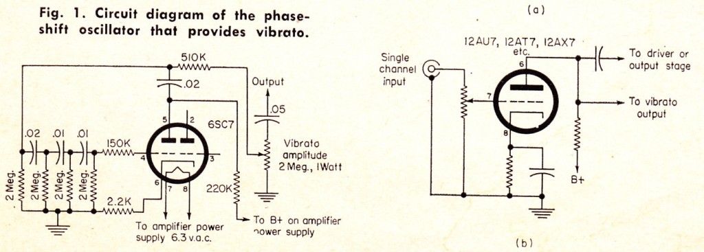
 Download a short article from 1962 by one F.H. Calvert on the subject of adding a vibrato circuit to any vacuum-tube audio amplifier:
DOWNLOAD: Vibrato
Above, the schematics. These are not plans for a stand-alone device: rather this circuit (the schem on the left) is intended to be added to any resistance-coupled voltage amplification stage (for instance, the circuit on the right). It requires an extra single hi-mu triode section. The author suggests 1/2 a 6SC7 or 1/2 a 6SL7, but it would presumably work just as well with 1/2 a 12AY7 or 1/2 a 12AT7, with maybe just a slight change to the 2.2K cathode bias resistor (can anyone tell me what the single-triode sub-miniature equivalent of the 12AY7 and the 12AT7 are? Do they even exist?) I have not built this circuit yet so no promises. A few observations tho: I find it hard to believe that this is actually a vibrato device; it seems like it’s likely a tremolo circuit. It looks very similar, in fact, to the trem circuit in the ole 18watt Marshall combo. Also: if it’s worth building, it’s certainly worth adding the speed variation pot. Contrary to what the author suggests, my best guess would be to replace the left-most 2M resistor with a 2M pot PLUS a fixed 470K resistor in series. Def gonna try adding this to the next Recycled Champ that I turn out.

9 replies on “Add Vibrato (?) To Any Tube Amp! (1962)”
6C4
“Q. You like Champs.
A. Yes, I like Champs a lot. Can’t go wrong there. “
http://leftyshefty.blogspot.com/2012/07/interview-with-amp-nazi.html
I have 6av6 in my 50′ amp.
What values of components did you use for the single-channel amp stage?
Also how can you design an amplifier using the schematic listed
Hi Johny. Regarding the schem om the right: there are no component values listed because that diagram is intended to represent a ‘Generic’ triode amplification stage; I.E., the trem circuit described will work in ANY amplification stage with that general architecture.
Regarding your second question: neither this post, nor anything on this website, is intended as basic instruction in building amplifiers; this is more’by-techs-for-techs’ content if you catch my drift. If you wanna learn the basics, I highly recommend you pick up “The Tube Amp Book” by Aspen Pittman or Jack Darr’s “electric guitar amplifier handbook.” Either one of those can get you started. Good luck! c.
If you want to build a guitar amp but have little experience cloning a Fender is far and away the best place to start. You have readily available schematics, but also the parts layout and widely available transformers and every other part. Building electronics is actually 90% mechanical.
You will need the right tools and test equipment. You will also be way ahead to buy the correct parts new. Too many people try to build stuff out of stripped junk and wonder why it blows up in two weeks.
Agree with all that
I spent years ‘salvaging’ foil caps and resistors from old equipment. Its not worth it. Transformers are worth saving tho. So long as they are relatively rust free.
Hi!
I like these schemes because of their simplicity. I have recently built an SE 5 watt amplifier and I am deciding if I put in some tremolo circuit. Can you please tell me where I want to feed this circuit? Am I supposed to wire the output from preamp 12AX7 into the grid of this circuit tube? (pin no.2?). Also is it better to put it in front of EQ or behind it? I am asking because my amp has the corrections after signal amplification.
Also what values of B+ do I need? I think I have something above 200 VDC on my source. Thanks a lot for your input. Any answer will be appreciated as I really need to find something simple.
sorry, in fact I meant pin three of course 🙂