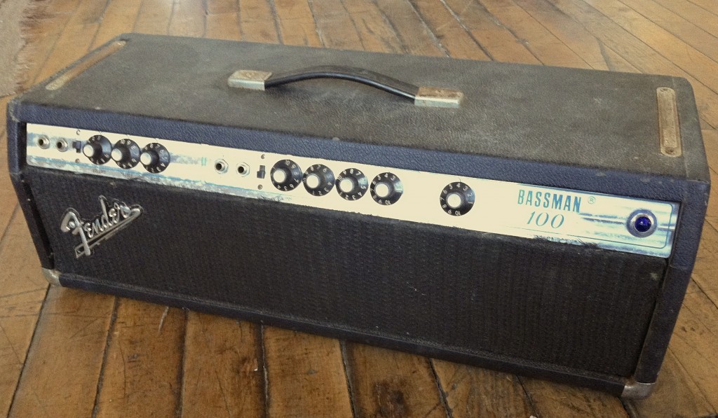
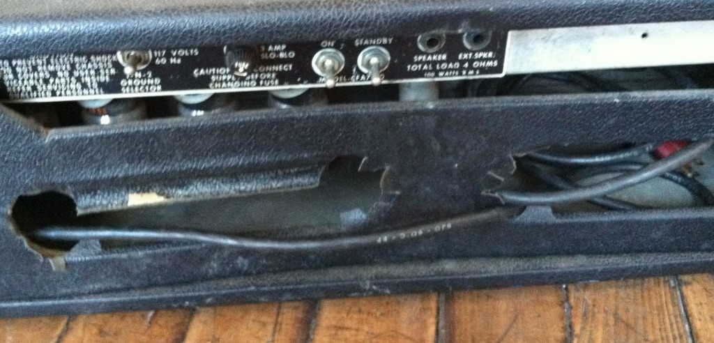
 Of all the non-PCB tube amps that Fender ever made, the one most likely to rot away unloved in some dude’s attic is probably the Bassman 100. Too wimpy to be a useful bass amp, too loud to be a good studio guitar amp, and too boring for anyone to give a shit about, the Bassman 100 is just begging to be a parts-donor for someone else’s broken Twin Reverb. Naturally, when I saw one at the flea market this weekend, I couldn’t resist buying it.
The seller told me, plainly, that is it needed work; “It hums and buzzes; the guy said it needs a power transformer.” ‘The Guy’ in this case was apparently an electrical engineer who worked for CBS and held several patents? Some kind of electronics genius, I was told? Cum Grano Salis, as the senator said, but I was scared enough that I almost didn’t buy it. Because there are only two parts in a 100-watt tube amp that are expensive to replace: the power transformer and the output transformer. In that case of an 100-watt tube amp as undesirable as a Bassman 100, either of those conditions would make it literally not-worth-fixing. The seller, whom I deal with often, agreed to take it back in a week if I insisted. Fair enough. $140 crosses the table.
As I have commented on before, a tube amp that buzzes and hums is not a bad thing; the fact that it is making sound at all means that at least the power transformer, rectifier, output tubes, and output transformer are working. The rest of the stuff is cheap enough that it shouldn’t be a major deterrent.
I took the thing back to the shop, plugged it in, and guess what: not only did it hum, but it worked, and it was loud. It was loud and it was making bad smells and blowing fuses in 30 seconds also. So oh-keeee… Here’s what needed to be done to get this thing back to ship-shape condition (and no, it did not involve a new power transformer).
This one is gonna be long, and very technical, so please click the link below to READ ON if yr so inclined… (short story: the amp worked great and sounded great after about 3 hours of work and $50 of parts…)
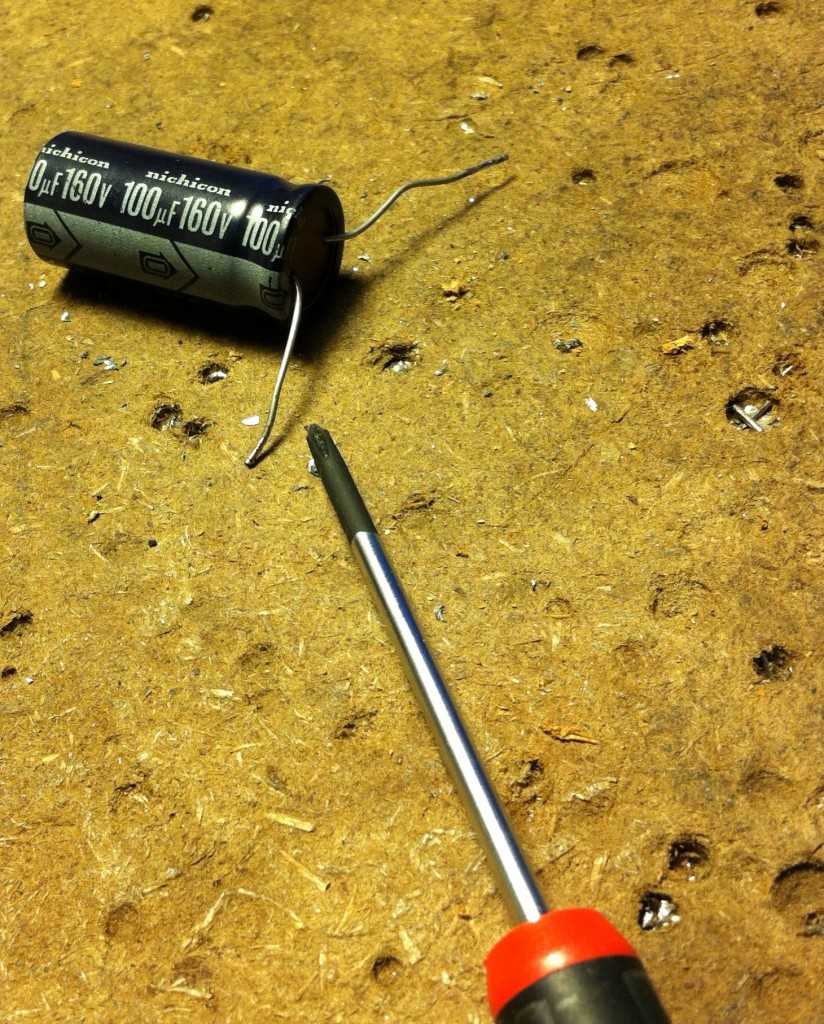 It’s never a bad experience to service a vintage Fender amp because Leo Fender made them to be serviced easily. The chassis slide right out with a minimum of fuss, everything is arranged very logically, it’s a snap. Pulling out the chassis here, the first thing that I noticed was that the first bias-supply filter cap was completely disconnected from the circuit. One leg was just flying free. See above: someone had very unwisely used a radial cap where an axial cap was intended. When I was starting out in this field, I made a similar mistake once; it’s important that parts have a good mechanical fit, especially in the case of a unit that is going to be moved and jostled around a lot like a guitar amp. the top-heavy nature of this big radial cap (no doubt aided by a poor solder joint) made it leave the party too soon.
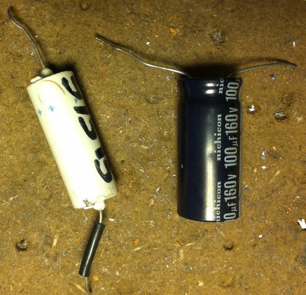 After I replaced that radial cap with the proper axial, I measured the bias voltage at the grids of the 6L6s: zero. There was no bias. Yet again I must say: It Is A Fkkng Miracle This Thing Worked At All. Turns out that the 2nd bias-stage filter cap (above, left) was totally shorted and simply leaking the bias supply to ground. Great…
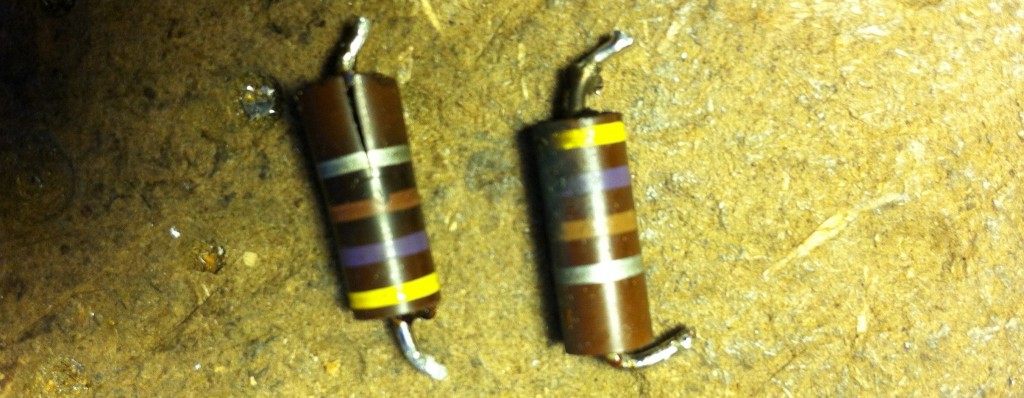 …and which would explain this (above), two output-stage screen resistors which were positively cooked! Look at the one on the left! BTW, the grid-stopper resistors on these two tubes were also toast; in fact, the drastically underbiased output tubes were throwing off so much heat that the back panel of the amp had become warped and all of the glue that held the tolex in place had melted off:
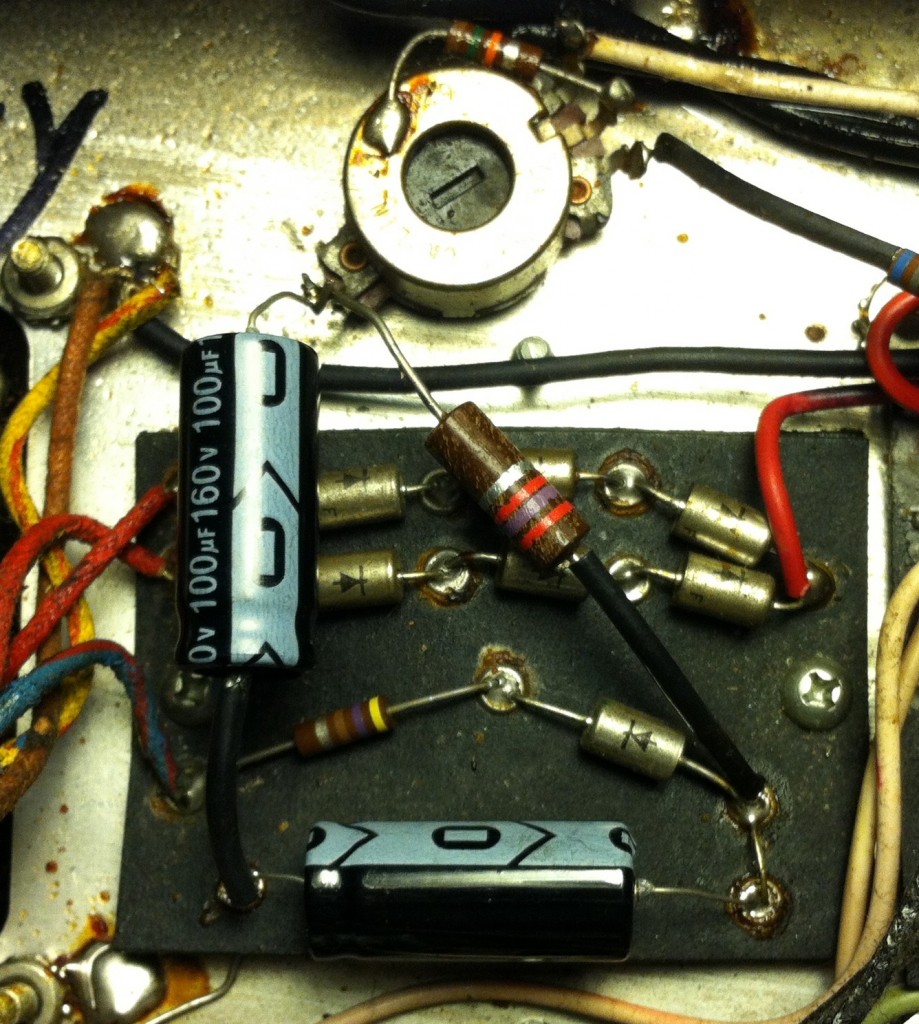 Above, the bias stage with the two new filter caps and a new 2700 ohm dropping resistor, which was necessary to get the bias voltage in line with the schematic. Because… like most big Fender amps of the 70s,there is no bias level control. That pot you see there is rather a bias balance control: you can change the relative bias of one pair of output tubes verses the other (Fender called this a ‘tube matching control’), but there is no simple adjustment for overall bias.
So what else…
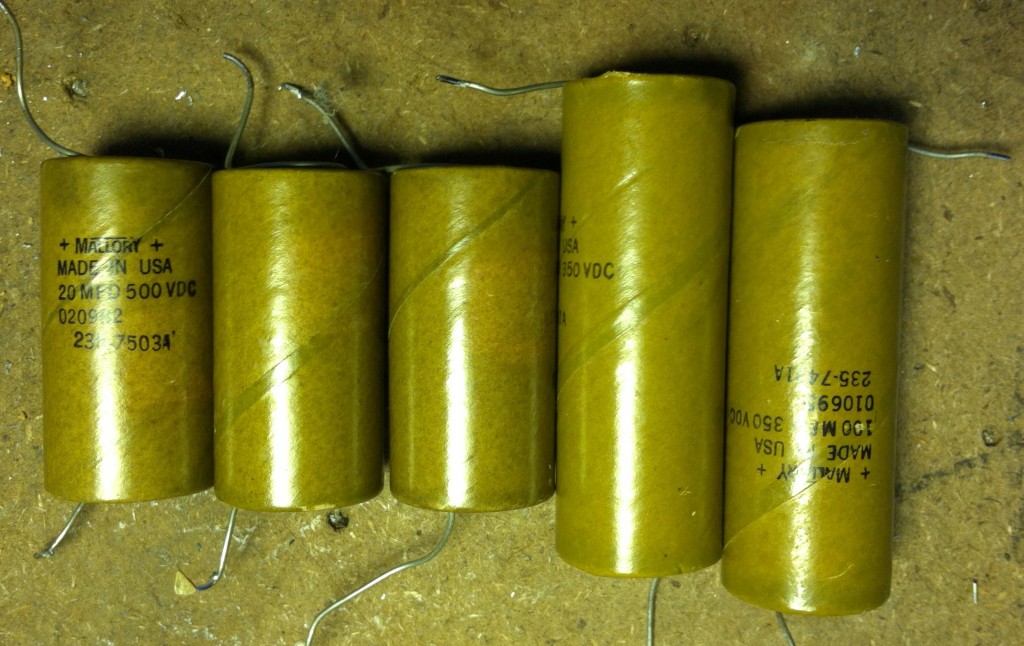 Circa ’75 filter caps should prolly be changed…
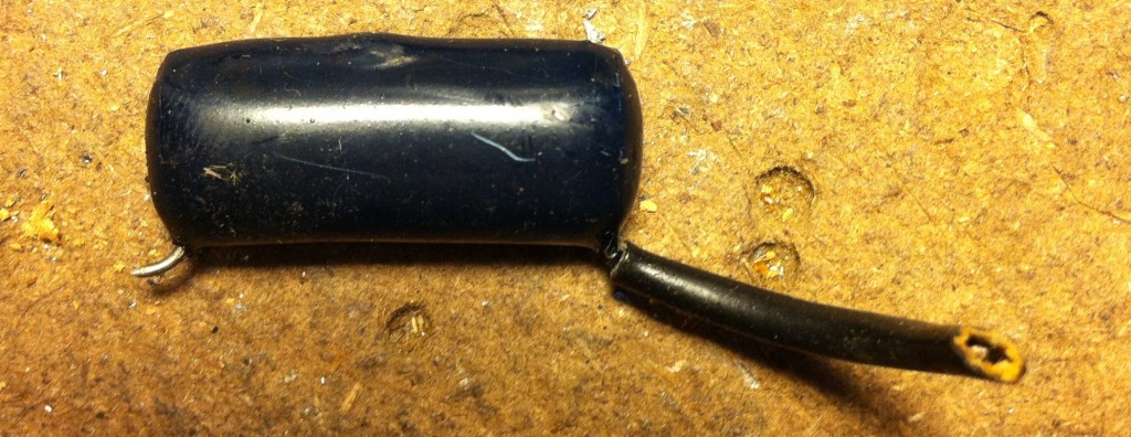 ….remove the ‘death cap’ (because… which end of the AC power line do you want to give a path to ground? How about neither?)
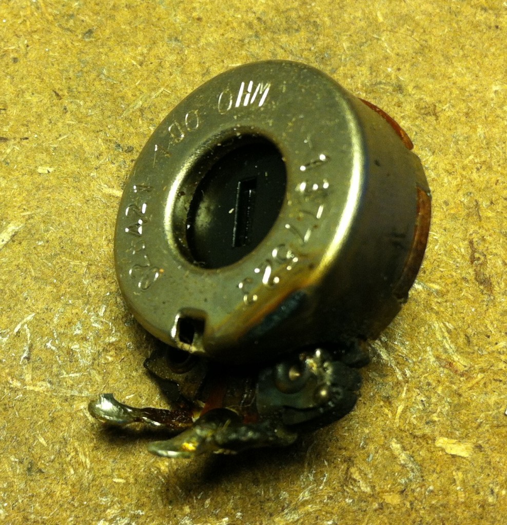 Oh and wow! This is a good one. Above is a toasted hum-balance control. How this ever happened I have no idea. In all of the 100s of vintage tube amps I have serviced, I have never ever seen a cooked hum-balance control. Bizarre…
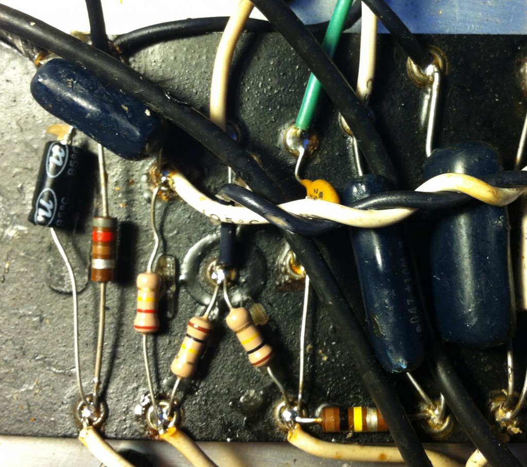 Alright so what else… well, after I did all of that above-mentioned ‘obvious stuff,’ the voltage throughout the amp were all fine, it was working fine, no hum, and it stopped blowing fuses. Now’s the fun part: chasing down the intermittent noises and crackles and bullshit that seems to always poke out once the hum+buzz have faded (kinda sounds like a typical recording career actually…)
Above: the preamp of the ‘Normal’ channel after replacement of 4 components. The ‘BASS’ channel worked fine, no noise whatsoever after I replaced the tube.
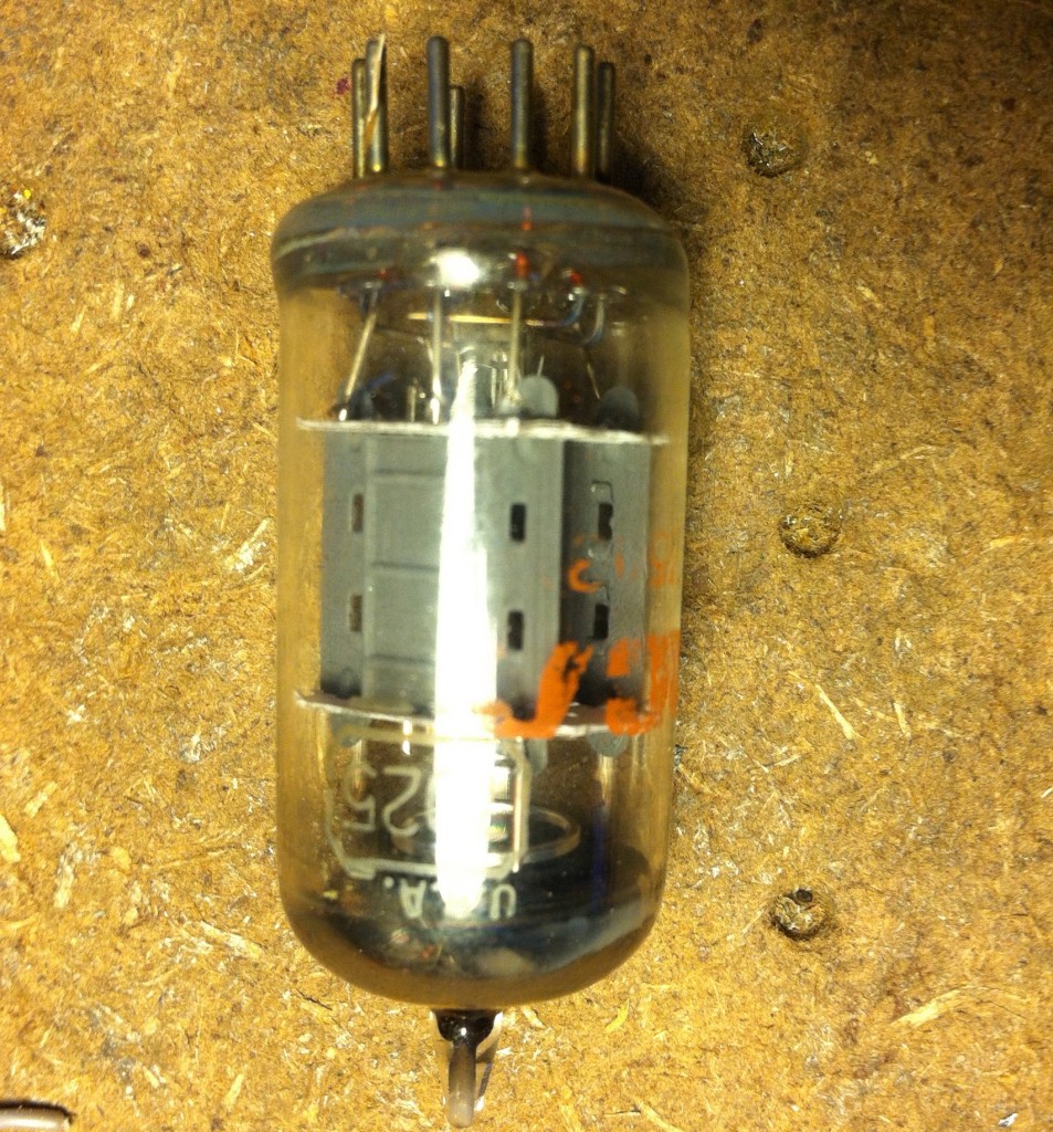 Above, the (likely original) RCA 7025 that lost one stage sometime between initial testing and final testing of this amp. Swapped it out with am NOS Sylvania and all was good… plus I had a good way of knowing just how quiet this amp should be. ‘cos the ‘Normal’ channel was noisy.
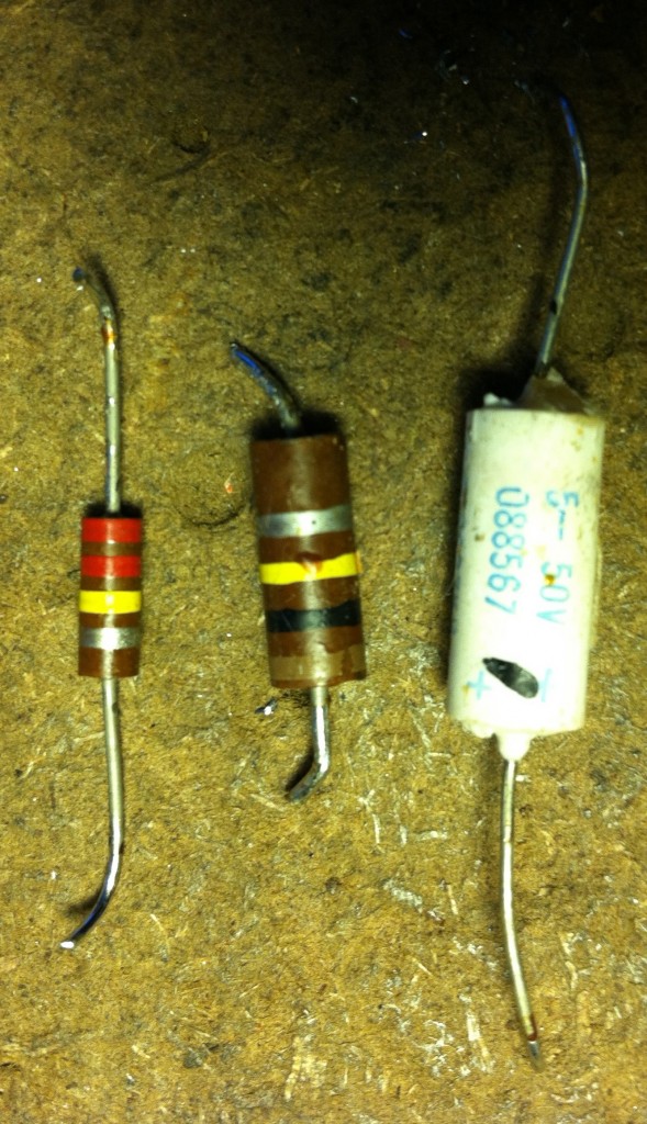 When one encounters a noisy (crackley, hissy, whatever) preamp stage, it’s generally due to plate-load resistors that have just given up. Plate-load resistors are the (generally 50k – 220k ohm) resistors that tie the B+ supply chain to the plate of each tube stage; the precise value of the B+ resistor (relative to the tube type in question) largely determines the overall gain of that stage, all other things being equal of course. NEways… these ‘lil guys drop a lot of voltage (200 volts in the case of this amp) by turning that voltage into heat; you try doing this for forty years and tell me how you feel. Anyways… swapped ’em out (a 100k and a 220k); noise persisted. Turns out that the cathode bypass cap of the 2nd stage was fucked up. I was able to determine this based purely on mechanical inspection; it was a bit swollen on one end. Swapped that and We-Are-Done.
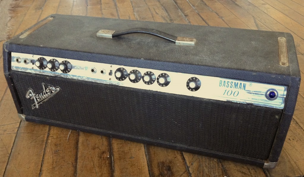 Amp now works great, sounds… fine, as good as it ever did, I imagine… I don’t know how many tracks I am ever going to cut with this thing, but who knows. Who ever, ever knows.
9 replies on “‘The guy told me that it has a bad power transformer, and he’s some kind of genius’”
The best guitar amp tech I knew had a bench supply with adjustable B+, bias, and a fused metered heater supply. Tough dogs he fixed by opening the transformer circuits, soldering on wires to the supply, and powering up. Shorts showed up instantly. He said that’s how his dad fixed old radios in the 40s, fast and profitably.
Also kept him from putting time and parts in a set not worth fixing because new iron wasn’t worth it.
Would some amps, have two hum balance control pot?
I have an amp I’m fixing. And it has two 100 ohm pots that are seriously rusted.
The amp itself is having trouble. Could those pots be the problem?
Hi Alex. i have never seen an amp with two hum balance controls, but then again there is a lot in this world I have not seen. I really can’t answer your question based on the little information that you have provided… but if it’s rusty it should certainly be replaced.
What kind of amp is it? DO YOU HAVE A SCHEMATIC??????? Until you really know what you are doing it is a no go item. No have schematic, no go further.
Got one of these coming in this weekend and we have been debating dropping in a half power switch, just lift the cathodes of a pair of the output tubes, to get more use out of the thing, seems like a good mod, but I haven’t seen the amp yet.
well good luck. half power switch is a good idea, and remember that this will change the expected speaker load to 8 ohms (rather than 4). I just got a new quad of 6L6s for mine, v v v curious to see how much this improves the sound. 6L6s have gotten expenseive! Rubys were the cheapest i could find, $60 for a quad. Just two years ago i was getting russian 5881s for $9/each….
You don’t need a half power switch .Just pull the outer or inner tubes and run it at 50 watts and 8 ohms .
Good shit. Nice to see a fixer-upper project come together.
And I appreciated the nice clear instructions (for those of us with only quite basic comprehension of circuits, like myself!)
Nice! THANKS.
Fantastic blog!