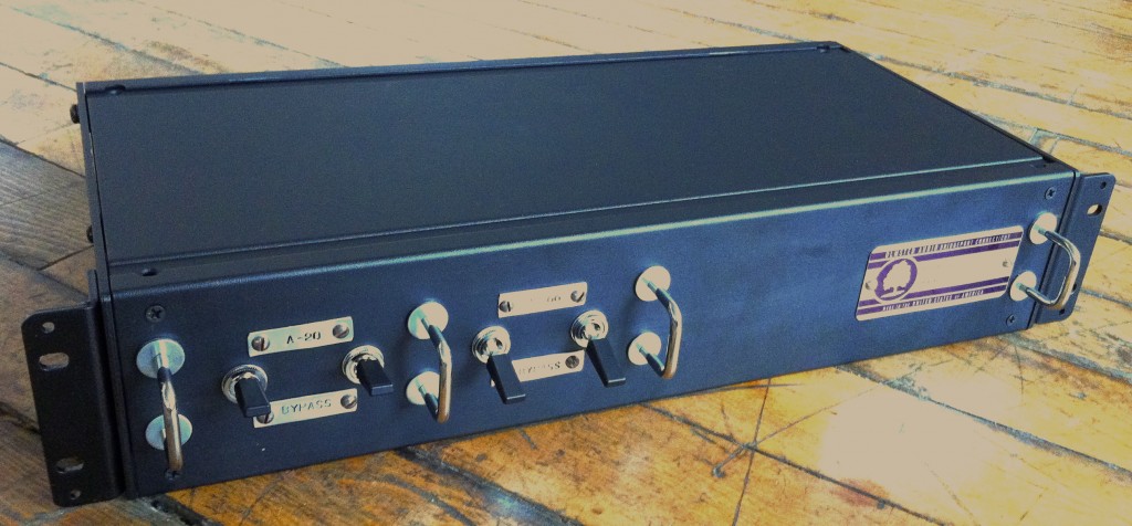
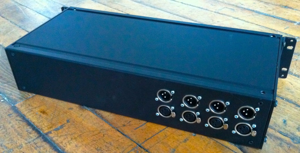
 Recently shipped this bespoke four-channel unit to customer P.G. PG sent me a pair of UTC A20s and a pair of Triad HS-66 600:600 transformers; he wanted a finished piece that would allow him to switch the transformers in-and-out of a signal path easily.
 For an explanation of the ‘transformer-as-signal-processor’ concept, see this previous post concerning a similar custom build. P.G. wanted his unit built as a two-space chassis so that he could add a third pair of transformers in the future if he wished; the front panel was precisely measured and punched so as to allow this to be done in a visually harmonious manner.
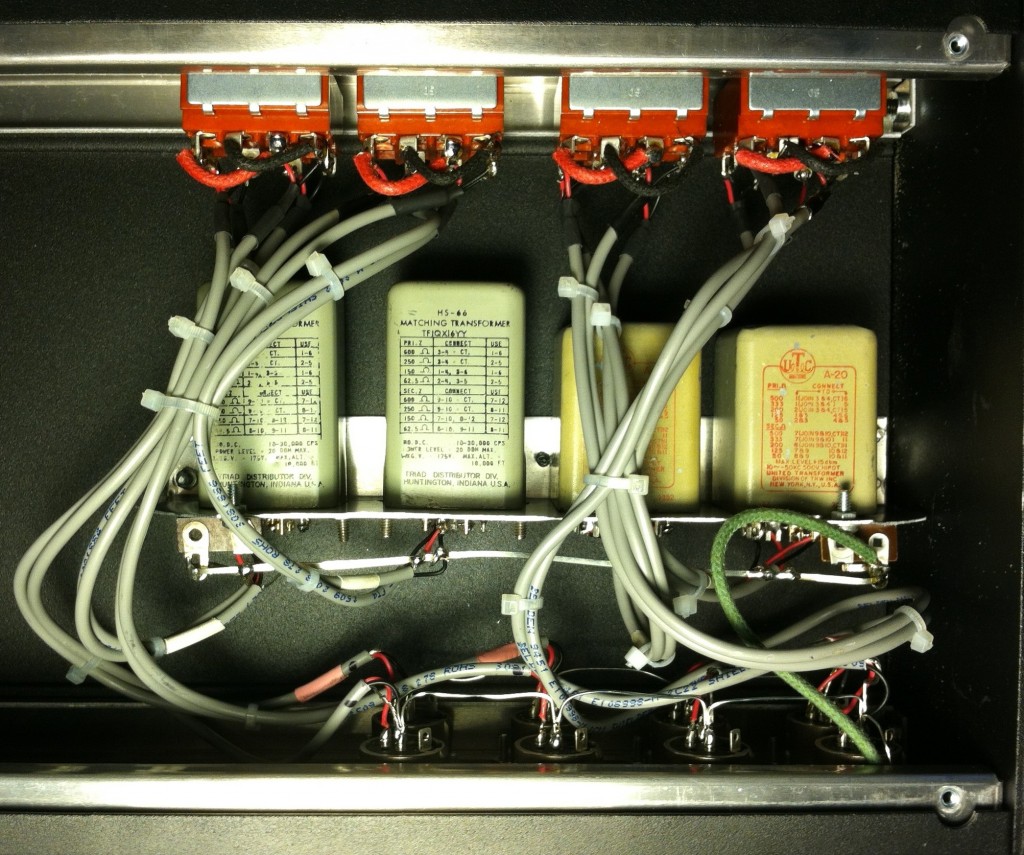
 Above, the inside of the unit. Belden 9451 wire and the same 12,000 watt (no typo) 4PDT toggle switches as the prior build. So how does it sound? For those of you who are curious about commissioning or DIYing a piece like this, here are my impressions.
First, the ‘hard facts,’ measured using sine waves at +10db.
UTC A20: Insertion loss approx. 0.2 db. down 1 db at 12hz, down 1 db at
65khz. Otherwise flat.
Triad HS66: Insertion loss approx. 0.1 db. down 1 db at 10hz, down 1 db
at 60khz. Otherwise flat except for a bump up around 10k.
As fast as listening test (with music, not test tones): and this is obviously very subjective: the UTCs are very very subtle. Bass is little more organized but it’s really hard to say. They are just too perfect I guess. If they are run them at full protools level (+22) the user will likely hear some color, as it is outside their stated linear range. But at +10 there is little effect.
On the other hand, the Triad HS-66 definitely have a sound: at first I thought that they were bass shy, but the sweep test denies that. To my ears, they make everything sound more forward and aggressive.
4 replies on “Transformer-As-Signal-Processor: Another Custom Build”
The Koreans love to do this. They will part out a certain piece of equipment and put the transformers back to back in the signal path from CD players.
Chris, this is interesting. I have done a similar concept using a spare patchbay, two rows, TRS. I wired it somewhat non-standard. Basically, the left side top is left channel input, left side bottom is right channel input. Right side top is left channel output, right side bottom is right channel output. I bring sources and out of the transformer panel from my main patchbay, which is also TRS, but set up more traditionally.
In between the ins and outs on the transformer panel are a bunch of different transformers, wired in horizontal pairs with left being input and right being output, so the signal always flows left to right for each channel. I have a pair of A20’s in there, also Triads but I don’t think 66’s. Also a pair of Langevin repeat coils (that can stay linear all the way up to +28dBm) and a pair of old Thordarsen repeat coils designed to interface with the telephone system for remote broadcasting, from the 1930s. Also a pair of Ampex octal matching transformers and a pair of Altec octal matching transformers. All do sound somewhat different and all sound different from transformerless audio. I was thinking that a good add-in would be a tube stage with no gain but adjustable saturation — do you have any good designs for such a beast? Another cool thing about the patchbay is, you can stack the coloration if you ever want to (although it gets pretty hairy pretty quickly, especially if you start with the Thordarsens!). I have a separate panel with Daven 600:600 attenuators, so I can control the level going into any transformer with another patch, but caveat is to make sure to drive the thing with equipment that can really feed 600 ohms (ie almost no cheapo pro-sumer recording gear and no consumer audio gear). You could start the chain with a Henry Matchbox (which is pretty damn transparent compared to any of the transformers or a tube stage) if the source had to be something like a consumer phono preamp or tuner.
I happen to have all the transformers mounted in an old scrap chasis that sits under the rack and is connected to the patchbay via a bail of wires wrapped with plastic ties like you used inside your box, but it could be done much more elegantly. If I were more artistic, I’d assign a color to each coloration and then color-code my patchbay and the chasis underneath.
For me, the best way to judge the transformers’ “sound” is playback of an excellent solo piano recording, something like Kissin’s “Pictures at an Exhibition”:
http://www.amazon.com/Mussorgsky-Pictures-At-An-Exhibition/dp/B00005UED7/tomslinx
Patch that in from a really good DAC like a Benchmark, where you’re getting the full range of the piano and the full dynamics, plus you know the Benchmark can feed 600 ohms and not barf. Then you get a good comparison basis. Like I said, all the transformers sound different from the input signal, to varying degrees. And they all sound different from each other. With a piano, you’ll quickly find out how much level the transformer can take because it will fuzz or smear transients if it’s over-driven.
— Tom Fine
wow Tom sounds like you have taken this concept to its logical conclusion. send us some pics to post! i like the color-coding idea too.
I’m currently auctioning a pair (2) rare vintage Triad HS-3 audio input transformers to support a Thai elephant hospital. Check them out on eBay at http://www.ebay.com/itm/181556468331