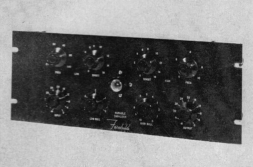
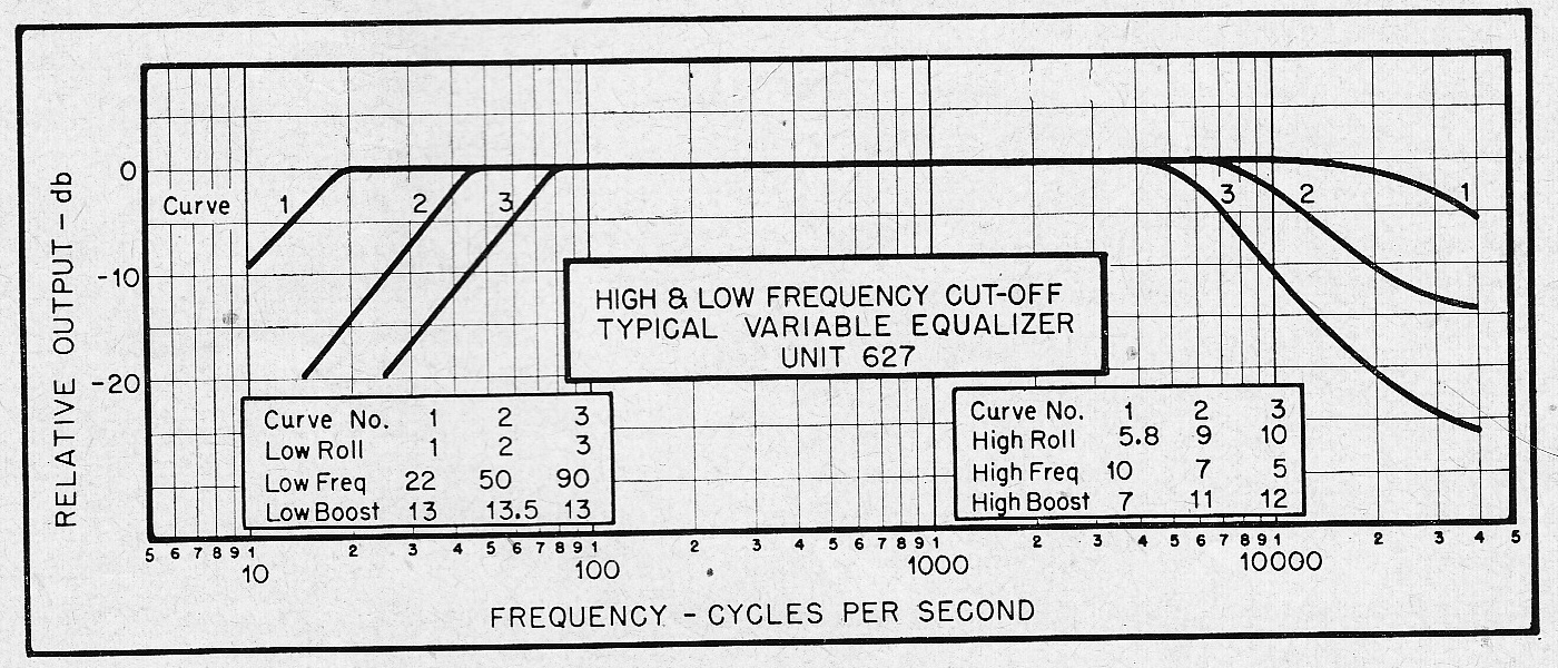
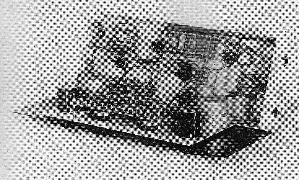
 Apologies for the poor image quiality; these came from the research department of a long-gone British broadcast-gear-manufacturer via some dampish papers that I purchased recently from a rare-books-dealer in London. I had never heard of the Fairchild 627 ‘Variable Equalizer,’ even though I recently sold an example of its (even-more-rare) predecessor the model 540, which in retrospect seems to be the ‘boost’ sections of the 627 plus a mic preamp plus a 20-watt cutter-head power amp. Well shit. Now i wish I had measured the values of the triple-ganged frequency-select pots. Why? We will get to that in a minute.
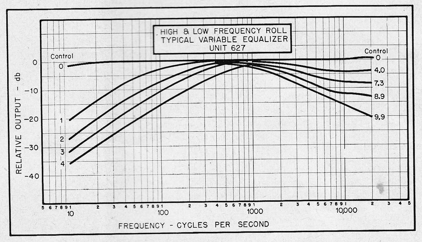
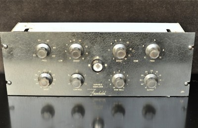
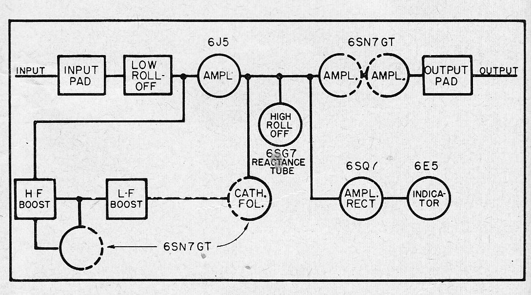
A quick google search suggests that there are thought to be only 5 Fairchild 627 equalizers in existence. One seems to have sold on eBay recently in the $7000 region. The 627 is a line-level EQ with continuously variable low and high bell boost sections as well as high and low roll offs. Unlike a Pultec, though, it is an active EQ, and it uses some pretty unusual circuitry – especially the high-cut section, which I don’t comprehend at all.
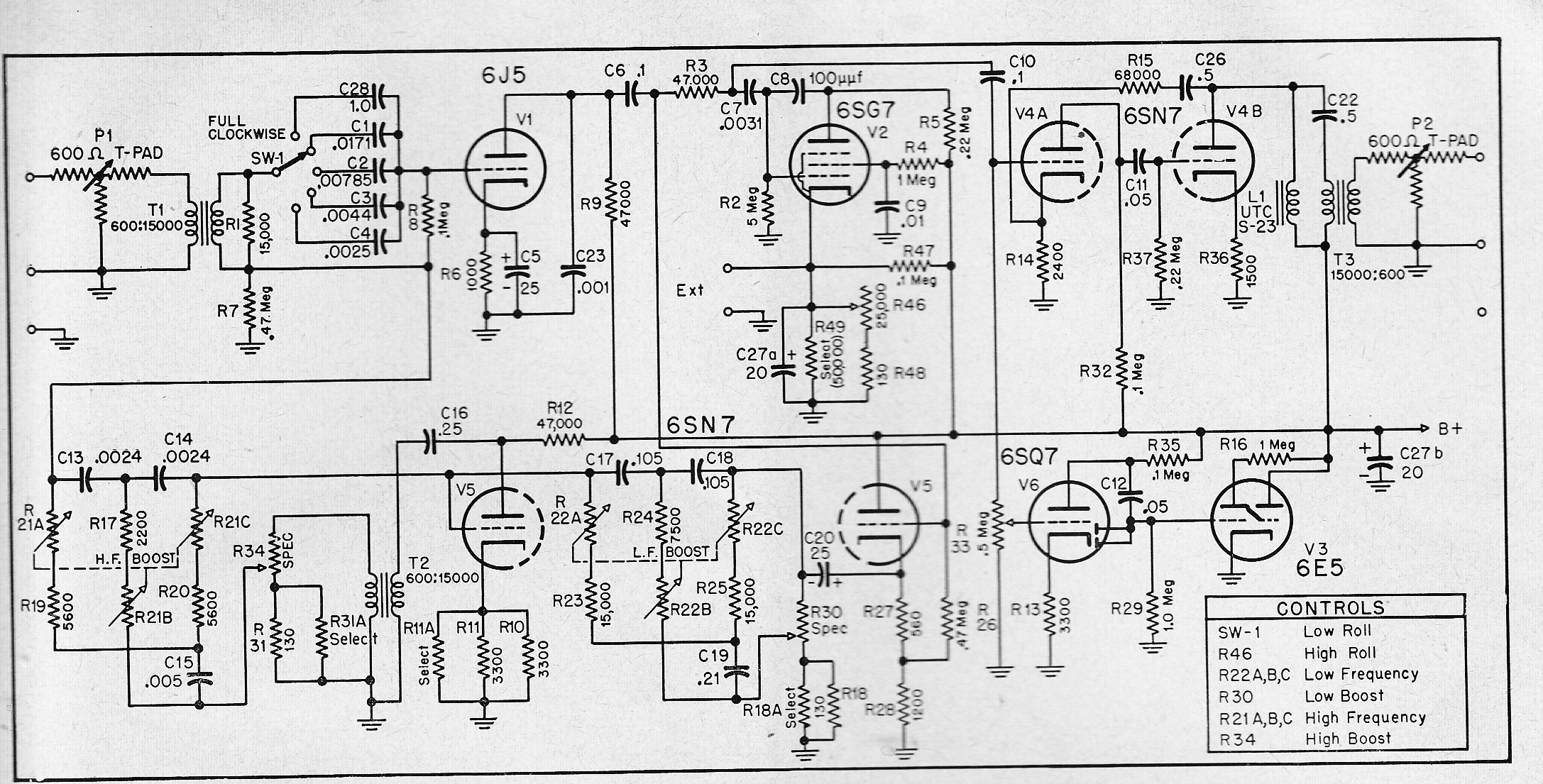 One point to note: T2 should be wired to reverse phase. I was v excited to find this schematic, because it seems like a pretty easy piece to build – there is no mention of the proper B+ voltage, but 250 is generally a safe bet; there are no weird inductors (the UTC S-23 plate-load choke is an off-the shelf part, so we know its specs -5000ohm DC, 300 henries); the audio transformers don’t need to handle DC and the turns ratios are spec’d: BUT: But. Those triple-ganged pots. WTF do we do about them?
Can anyone crack this case? Any insights, pls let us know in the comments section.
On the plus-side: at very minimum, this schematic does reveal an excellent and easy way to implement a 6E5 seeing-eye tube simply paralleled to a grid in the audio path. So at very least, now i know how to use those v excellent things in my mic preamps. Way more evil than a VU meter.
Also: the 6SN7 output section is a neat little self-contained module; def worth trying it with a Hammond 156C choke and an Edcor 15K:600 1/2 watt. The 156C is the closest modern part to the S23 spec; it is rated 150h and 3.7K ohm, seems close enough? I used onna these on a hunch in my OP6-semi-clone and it worked just fine in that application, so I am guessing it may work fine here as well. 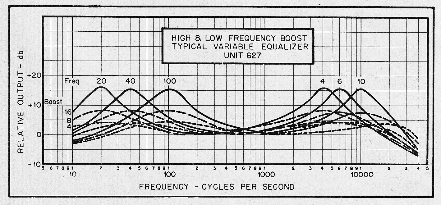
12 replies on “Lost to time: Check out the Fairchild 627 Equalizer circa 195nvr”
Hi Chris, did you get AML to make the kit of this old EQ? So cool man! What is your email? Thanks
Forrest
I don’t know who/what AML is, so no, I have no connection to their activities. CR
Hi Chris,
probably expensive as hell if you can even get a small qty, but there are options for the triple-taper pot it seems:
http://www.potentiometers.com/seriesS127.cfm
Any mention of what value they should be?
Thanks a lot for posting this; looks like a very cool piece!
By the way, i really dig your videos on Youtube, would love to see you do more; especially regarding equipment builds and studio techniques!
Cheers,
Steve
I was looking through American Broadcast History website in the Electronics magazine section under Annual buyers guide and came across an Advert from 1951 by Fairchild, it is on Page 246, this might shed some light on the 3 gang potentiometer, I suspect it is Type 746 which is linear type with a value of 100K.
Here is the link: http://www.americanradiohistory.com/Archive-Electronics/Buyer-Guide/Electronics-Buyers-Guide-1951-06.pdf
You will find the original article on the equaliser in Audio Engineering 1951 on the same site. Hope that helps!!!
[…] Most of the information on the Fairchild 627 Equalizer I could find online, comes from this link: https://www.preservationsound.com/?p=8602 […]
Regarding T2, the transformer is wired as such because the high and low rolls are not frequency cuts (look at any modern EQ), merely ‘Q’ width adjustments.
Please ignore this comment, I made a correction below:
The T2 transformer is wired as such because for this EQ, the frequency cuts are low and high rolloffs and not ‘band-reject’ -style attenuation cuts.
HI
On the three section pot R21a R21b R21c, R21b should be one-half of the other two sections. Also note that C15 is twice the value of C13 and C14. These correspond to the ratios of the classic Bridged Tee circuit. 100k for R21a and R21c, with 50k for R21b might be an interesting place to start
Hi
Quick calculation using f = 1 / 6.28 x R x C shows R21a and R21c to be somewhere around 10K for the hf EQ. R21b is half of that so 5K. For the low end EQ R22a and R22c around 50K and R22b 25K. As I recall, Fairchild was a major manufacturer of precision pots, so odd ball assemblies would not have been an issue for them…
Mea culpa: this is of course a Twin Tee circuit, not a bridged tee as I stated earlier.
I have been asked to make one of these and it will appear on Groupdiy under “627 from scratch” later this year (2022). The last post got the pots right 10k/5k and 50k/25k, the other resistors have to be a quarter of these values to get the range specified. I managed to work out a way of using ordinary pots with gear wheels connecting the three pots together. The 6E5 has limits of 125/250V but I think the optimum HT is around 230/240 V. The cathode follower draws 10mA at this voltage. The 6SG7 is a variable impedance with its cathode voltage set by the HT divider R47 and the 25k Pot, it loses the top end through the C7. What concerns me is the setting up procedure, there are lots of parts marked “select”. I guess this is to get the response curves shown above.
Please keep us informed of your progress!