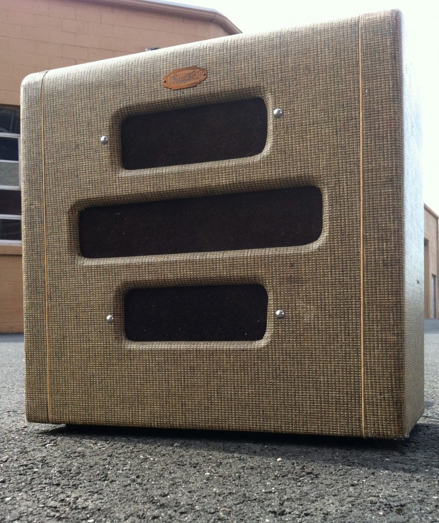
 A customer (J) sent me this wonderfully-preserved Supro amplifier to overhaul. It is a Supreme Model from circa 1950. Long-time readers may recall that this is the same amplifier model that I scratch-built a few years back as part of my ‘Field Coil Guitar Amp’ article. Click here for that earlier piece, which contains links to the schematic as well as lots of information what makes these early Supros such interesting pieces.
 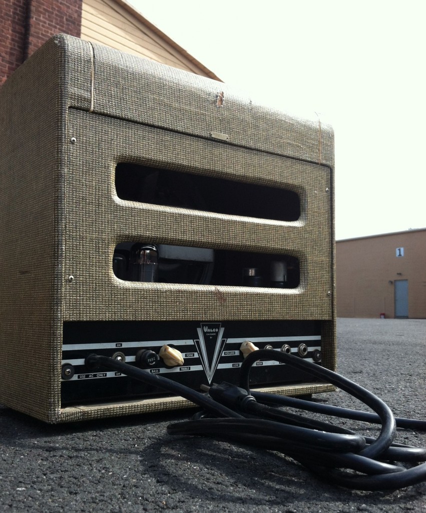 J had purchased this amp sight-unseen from the original owner, based largely on its excellent styling and strong cosmetic condition. It came with a matching lap-steel electric guitar. It was sold to him as ‘working,’ but what does that really even mean as far as a sixty-year-old tube amp is concerned? Anyhow, he received the amp, it sounded terrible, and he sent it me. Here’s what I did to bring it back to it good-as-new. Probably a little better.
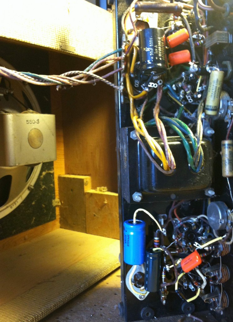 Above, a view inside the chassis after most of the work was performed. Since this is a field-coil amp, there are several wires running to and from the speaker/field/output trans, so it was quickest to perform the work at this slightly awkward angle. When I received the amp, it did in fact pass audio at a decent volume level, but there were some obvious deficiencies. The volume seemed to be a little low; there were some intermittent crackling sounds; and the sound was distorted at any volume level. The voltages were also all over the place. There was an expected 350 vdc coming off of the rectifier, but the voltage fell to 150 after the first filter stage.
First things first: change the filter caps. Even if the original filter caps were not the problem, they are sixty years old, and J bought this thing in order to use it live, so reliability is paramount, and filter caps are cheap so long as you use the small plastic single-units as I did above (as opposed to paying $40 for one of those identical-fit newly-manufactured multi-caps). I disconnected all wires going to the original multi-cap and left it in place.
Next: that crackling sound. In my experience, this is generally caused by aged pre-amp plate-load resistors. These resistors drop a LOT of voltage (which they do by turning it into heat) and they don’t last forever. Changed all of those out and the crackling went away.
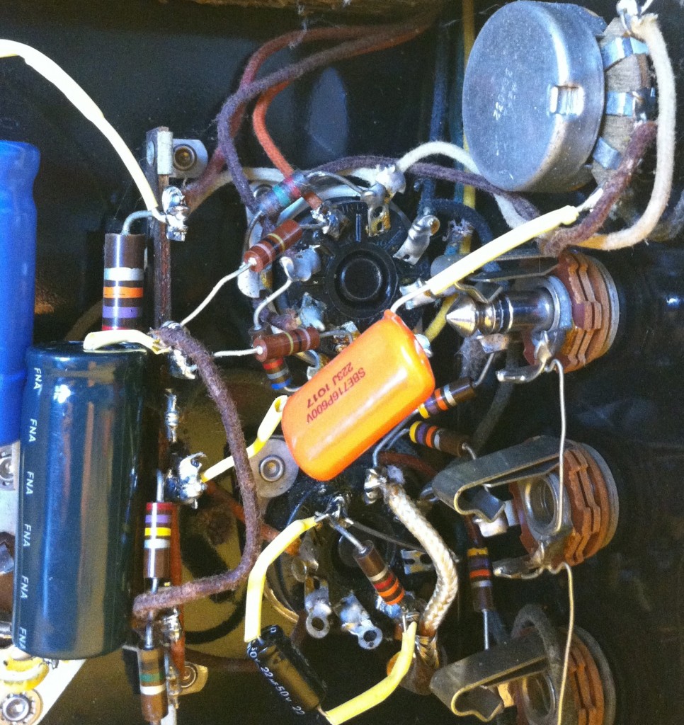
Now about that low B+ reading and the constant distortion: I had noticed that the volume pot had a slight crackle to it. This can be caused by one of two things: dust and/or mechanical failure in the pot itself, or there could be DC voltage present at the pot. The coupling capacitor ahead of the pot is supposed to block this DC, but these are 60 years old ain’t they. After a quick spray of contact cleaner the crackle was still there, exactly the same. I put the DC meter on the input of the pot and sure enough: 2 volts were present. This is not a lot (I’ve measured as much as 25 volts here in amps that are actually in-service) but it’s enough to cause some noise. I replaced the coupling cap with a Sprague Orange Drop (the big orange thing in the photo above) of the same spec and done. Noise was gone. The pot actually worked fine and did not require replacement.
Anyhow, the fact that this coupling cap had failed lead me to believe that the other similar caps in the amp were also suspect. And as it turns out, the two .02 coupling caps feeding the grids of the 6V6 power tubes were VERY leaky: I measured 22 volts+ present at the grids of those tubes. Since this is a cathode-biased amp, I would expect to see 0 volts DC at this point and around 20 volts present at the cathode. Instead what we had was an amp with a 100% bias error. It’s amazing that it worked at all. The 22 volts present at the grids of the 6V6s meant that they were drawing a TON of current, which explained the low B+ reading.
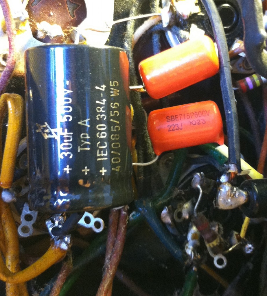 Replaced those paper caps with a pair of Spragues and that solved all the remaining problems. The amp now had the expected voltage readings all around and it sounded great.
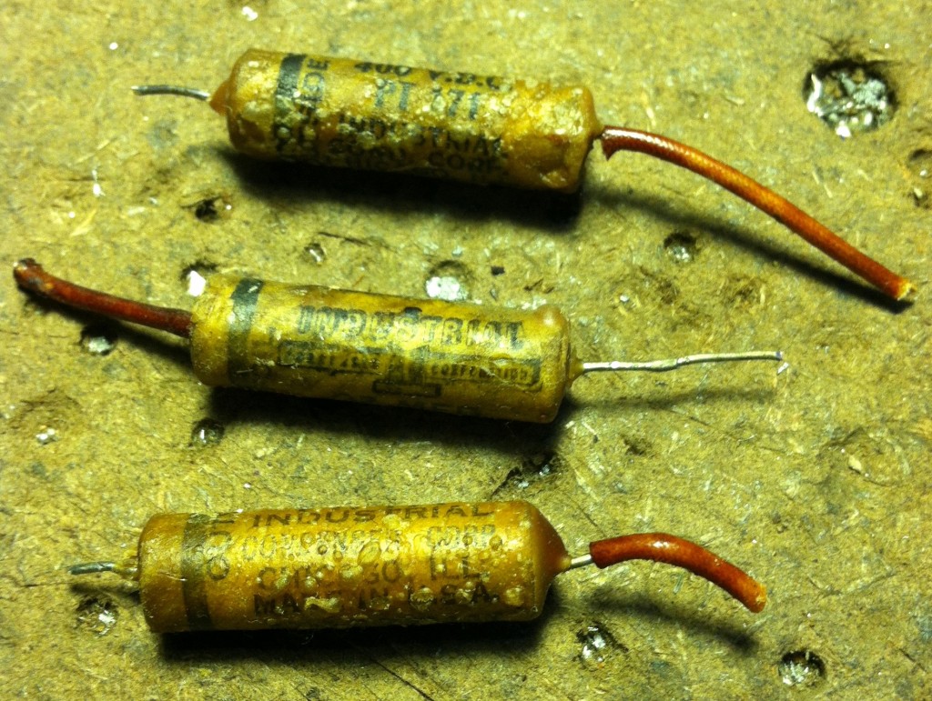 Above, the sweaty, disfigured, overall funky coupling caps that had gone so wrong. I can’t tell you how many amps I see that have bad coupling caps in them. It’s funny that so many guitar players, even those who couldn’t tell a filter cap from a resistor, will talk about replacing filter caps etc etc how much it improves an amp etc. Now, this is true, but old coupling caps are just as likely to need replacement. And unlike filter caps, it’s very easy to tell if a coupling cap has gone bad. Does it pass DC? Replace it.
So what else did this lil Supro get? New matched JJ 6V6s, to start with. I auditioned several NOS 6SC7s in the phase inverter position and none of them made any difference, so I left that tube and the rectifier tube alone. The 6J7 preamp tube sounded fine, but I was curious how much improvement could be gotten there, so I put in a 1620 (special selected low-noise 6J7 variant) and there was a marked reduction in white noise and less hum too (hum level had been low after the re-cap but now it was nearly gone). I added a grounded, 3-wire AC cable, removed the ‘death cap’ from the AC primary, and bolted it all back together. The amp sounds fantastic. Really, really great. Much better, in all honesty, to my DIY’d version, although how much of that is due to the speaker I’ll never know. I’ll end on this note: people seem to be under the impression that these old Valcos and Supros are somehow low-budget, cheaply made, etc., but I found quite the opposite to be true. This piece was extremely well-constructed, with very high-quality components throughout, and the soldering work was nearly flawless. For a very small amp that only weighs about 15 lbs, it’s loud, clear, and dynamic, and overall just a very cool alternative to a tweed fender deluxe for about 1/4 the price.
It’s very easy to service a previously-working amplifier that has ‘suddenly stopped working.’ I plug it in and start measuring the voltages, starting from the power transformer primary, on to the secondaries, then to the B+ supply, etc, the tube plates, the cathodes, etc., until I find a voltage that looks off. The component failure will likely be somewhere at that point. On the other hand, an old amp that ‘works’ but which has numerous deficiencies (crackles, hums, noise, distortion) can seem a little more daunting, but if one employs a similarly systematic approach, all issues will eventually reveal themselves. Even if a technician doesn’t have the service data on a particular amp, they have become familiar (through studying many amp schematics that do have test voltages indicated) with the kind of readings that one would expect to see on the grids, plates, and cathodes of various tube amp circuits. That’s a good place to start. The rest of it – learning which components are likely to fail, and what the symptoms of these failures are – learning all that stuff just takes time.
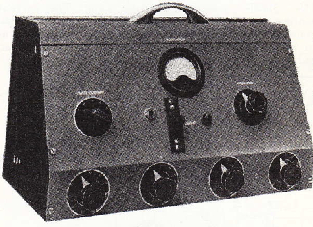
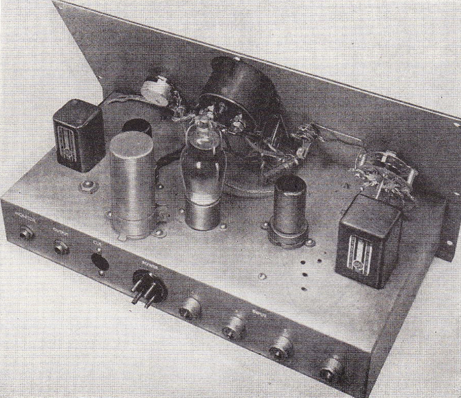
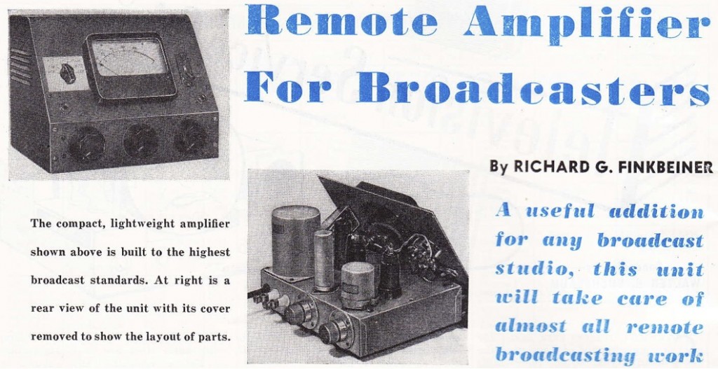 Download a four-page piece from RADIO ELECTRONICS, March 1950, on the subject of Build Your Own Two-Channel Remote Amp. Author is Richard Finkbeiner.
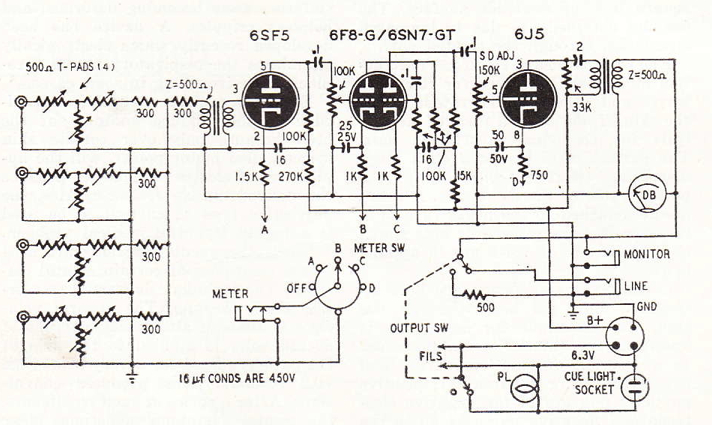
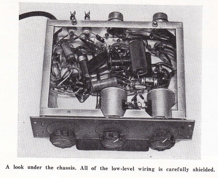 Again with those T-pads. Anyhow, we have here two 6J7 pentode stages in series supplying a 6F6 (v v similar to a 6V6) output stage. Here’s the schematic:
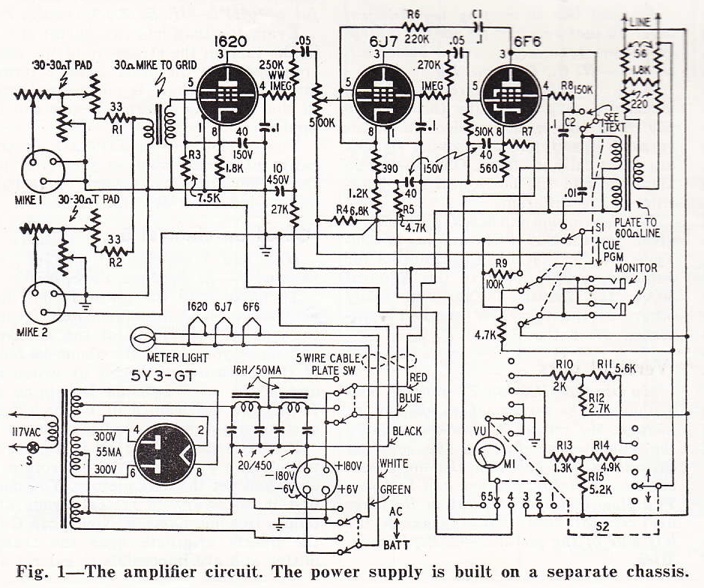
 The schematic is a bit opaque due to the fact that this piece is designed, ‘at the touch of switch,’ to become a cue amp – to receive signal, via its Station-Link, rather than send signal. Confused? The article will make it clear. Anyhow, if anyone has tons of time on their hands, it might be interesting to re-draw this schematic minus all of that circuitry. I would be v curious to know exactly which output transformer the designer used: a 5K to 600 ohm transformer that can handle 3 watts of DC and remains flat 30hz – 15khz? Sign me up. (It sure looks like a Langevin, but as I don’t have the early 50s Langevin catalogs, I can’t say which model it might be) I can tell you that even the modern Lundahl that I use in my BRDCTR can’t offer quite that level of performance, although Lundahl does promise it…


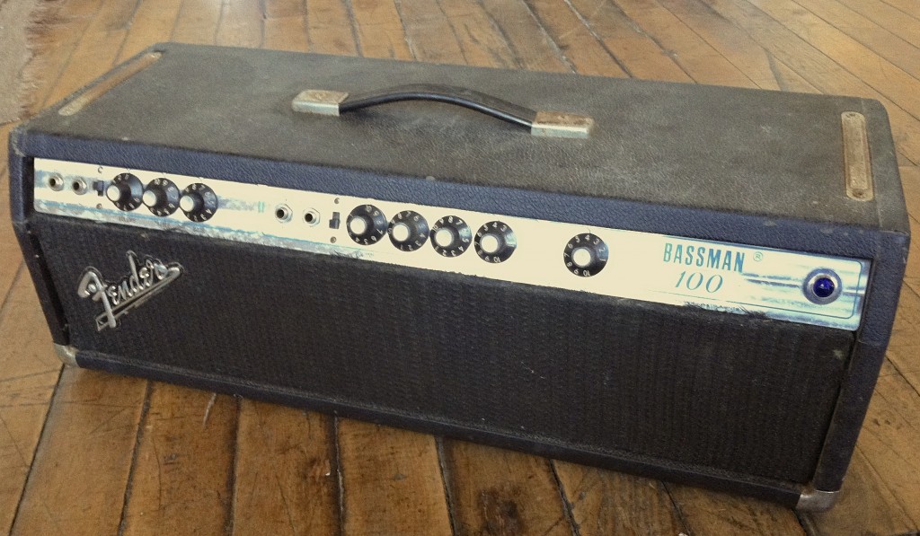
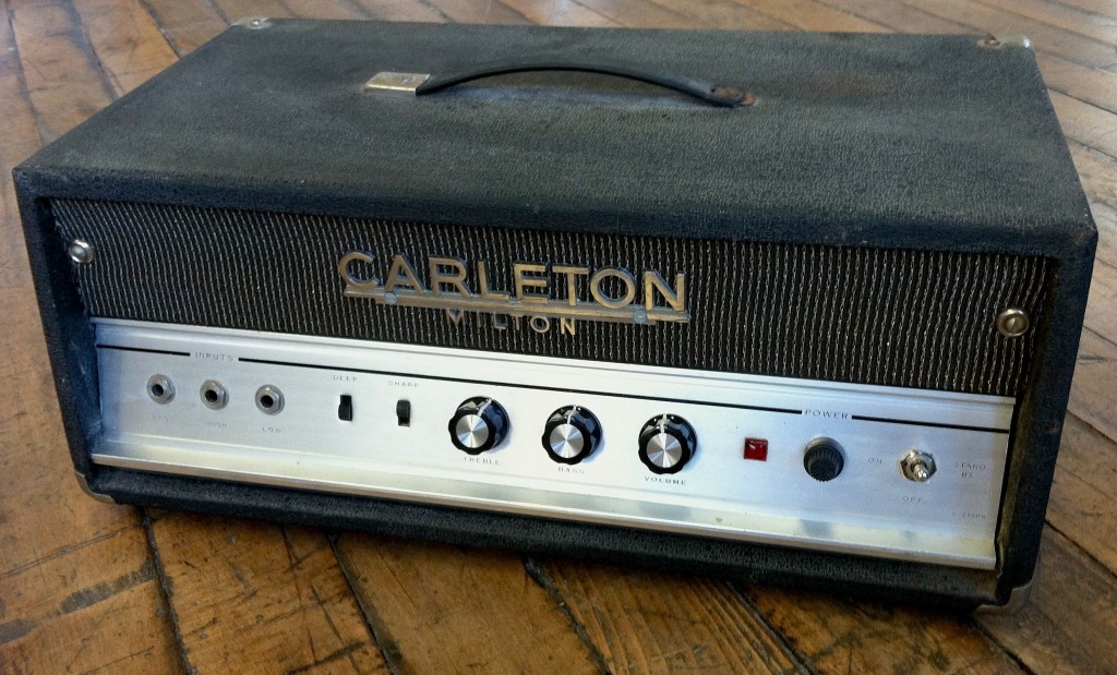
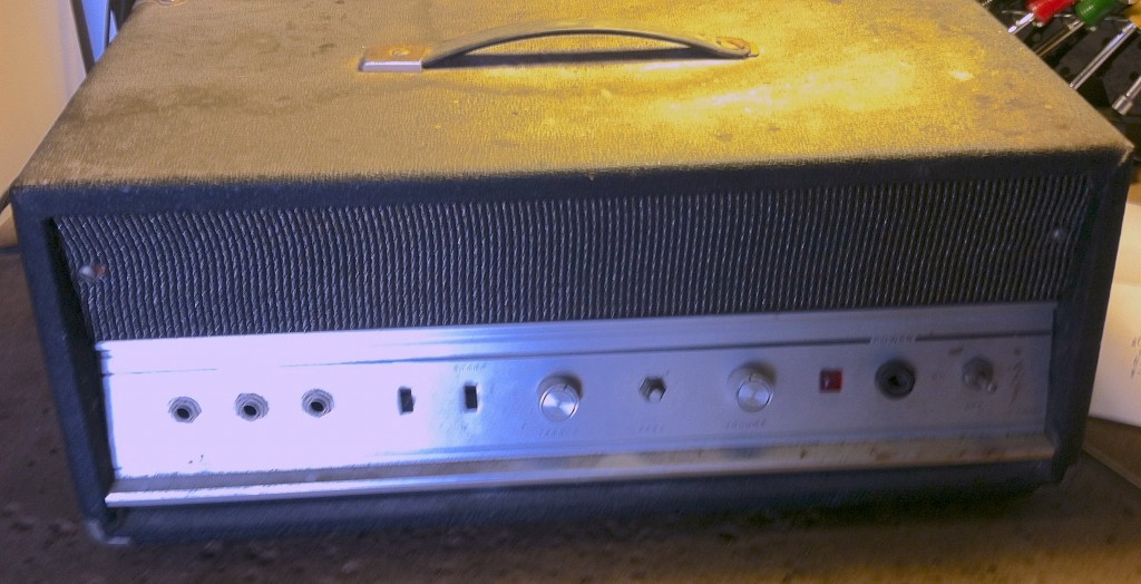
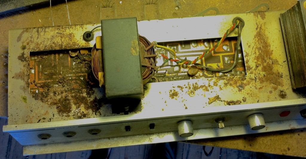
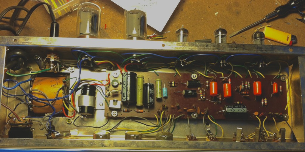
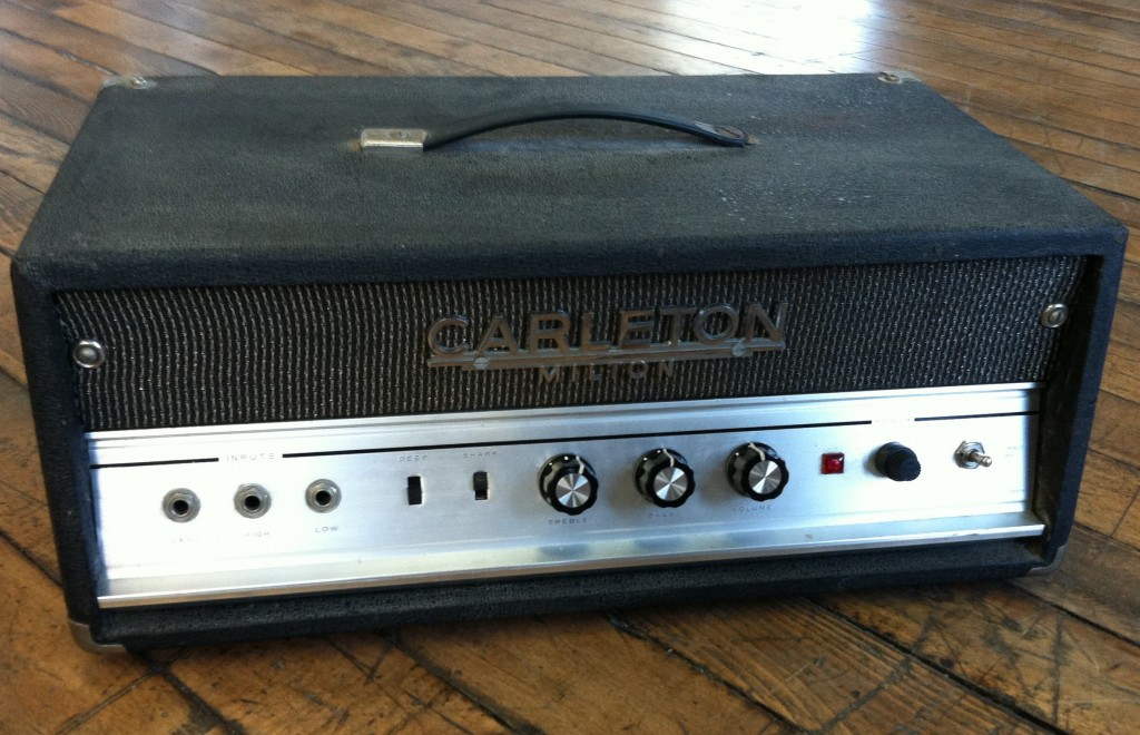 As far as the cosmetics go: one of the original knobs was missing and I didn’t have an identical unit in stock, so I replaced all three with some vaguely period-correct Japanese knobs. I also didn’t have a Univox logo plate to replace the missing original, so I added a name plate from the random-logo-drawer onto the front of the amp just because it looked a little odd with nothing there. Univox is now ready to go, much better than it was from the factory: better caps, better output trans, and much better tubes too. If this had been a repair for a customer, the bill would have been around $400 for parts and labor (assuming I used new Chinese or Russian tubes and a new O/T). $400 is clearly too much for a sensible person to spend on repairing a piece like this, as the street value for a properly working unit is only about $350. Had someone other than an amplifier serviceman purchased this thing, it probably would have gone into the trash or into another garage for the next 45 years. Now, if the Univox had been wired and assembled like a Fender amp, on a turret board, the repair would have taken half as much time and the repair could have been vaguely cost-effective. It was the goddamn awkward circuit board that made it take so long to re-fit. Proof yet-again that repairman-friendly construction practices do add significantly to the service-life of an amplifier.


