Categories
Altec Technical

Altec 436 Compressor: Taming the Output Level

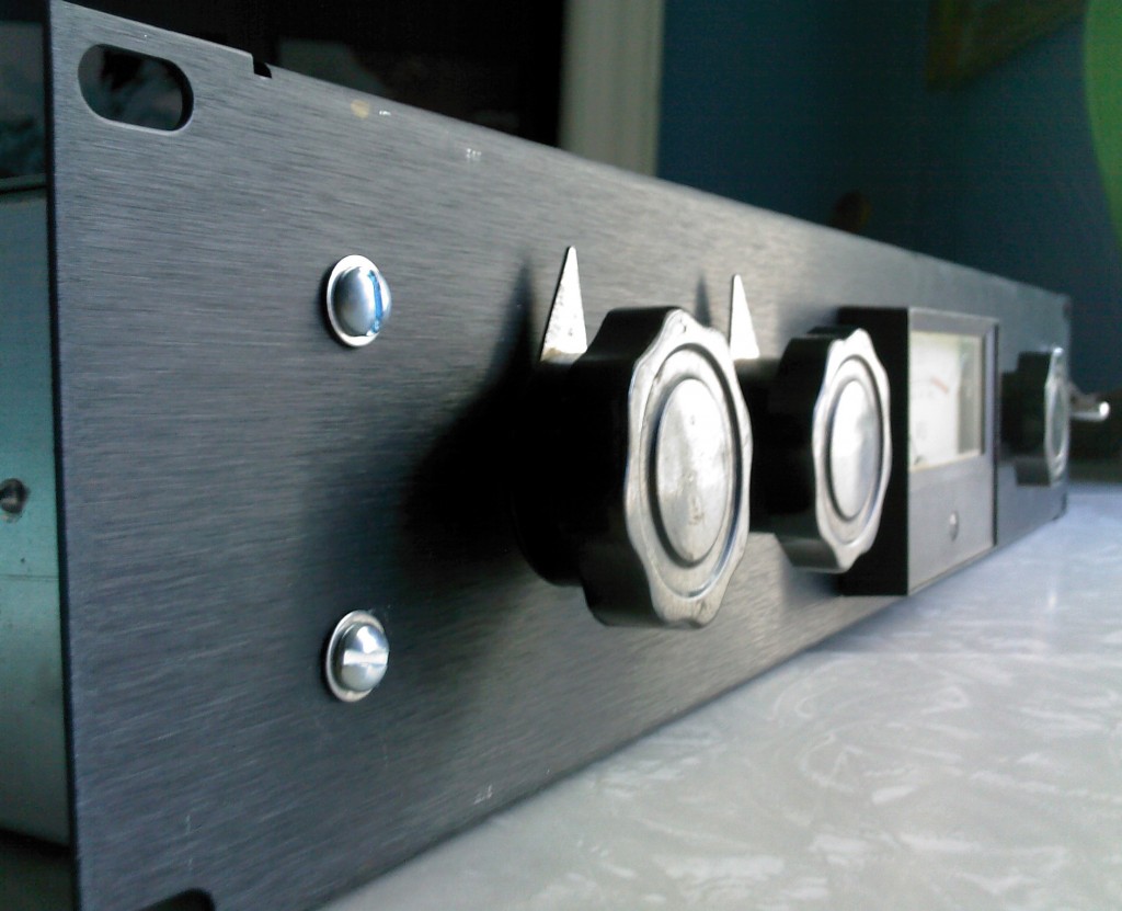
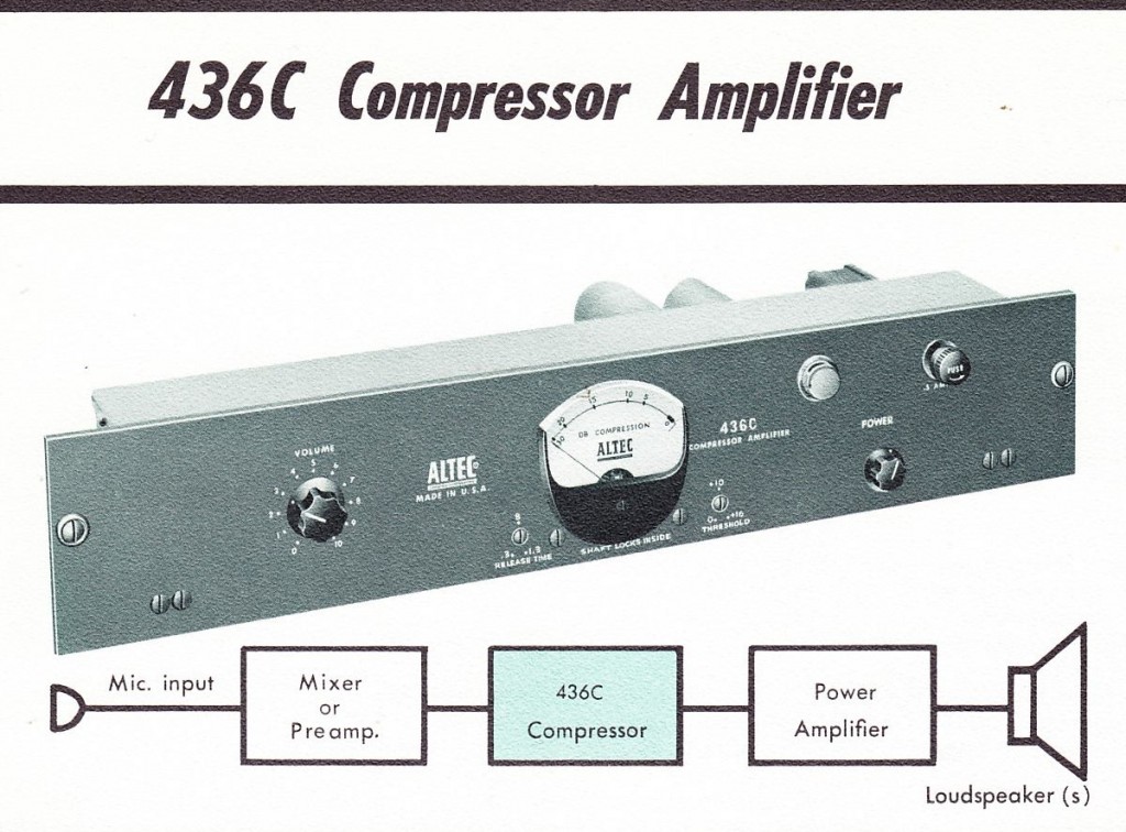
Ah the classic Altec 436C compressor (see here for previous coverage on PS dot com).

Here’s a fresh high-res scan of the original product-sheet (2pp):

DOWNLOAD:  Altec_436C

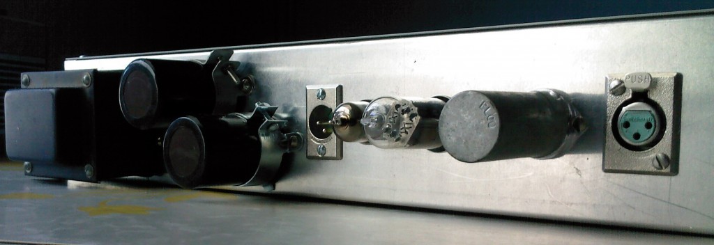
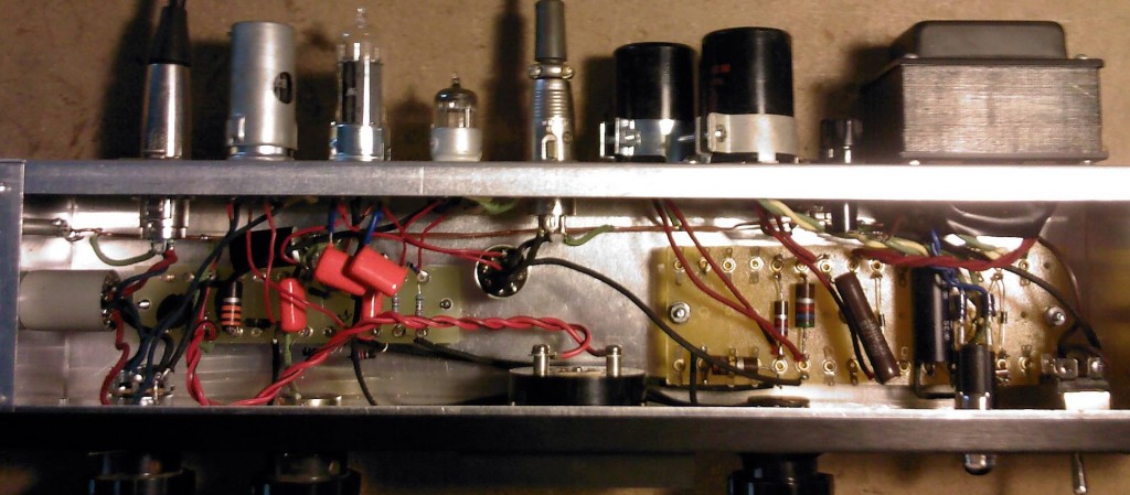
I built one of these some years ago and it really sounds great.  I used UTC ouncer -series transformers.  Don’t be fooled by the tiny size – these are very good units.  In fact, Ouncers are used in the early Urei 1176 as well as UA-175 and 176 compressors.

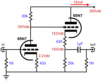
You can see how super-simple the circuit is. Aside from using a conventional power-supply circuit (rather than the voltage doubler that the original unit uses), i built mine pretty much exactly the same as the schematic.

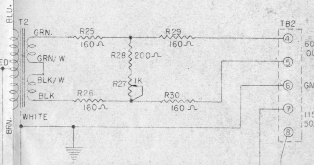
Now, if you look at the schem, you can see that there is no provision for an output control.  This is a problem because these things add a lot (like 20 db or more) level to whatever you put into them if you have the input control high enough such that the unit is actually compressing.  In the past I have gotten around this by using an outboard Daven H-pad attenuator that I mounted in a little box.  This is not ideal for ergonomic reasons.  Anyhow…  while studying the (very similar) Gates Sta-Level schematic the other day, I was intrigued by the very simple, very inexpensive variable balanced output pad that the Sta-Level uses.

It’s like $5 of parts. Five 1/2 watt resistors and one pot.   Based on information in the Sta-Level manual, adding this circuit after the output transformer of the 436C will provide a minimum 10db and a maximum 16db attenuation.  Perfect.  Now, it’s true that using this control will vary the effective output impedance of the unit slightly; but according to Gates, “This pad has been carefully tested to assure that the small impedance mismatch resulting from this range adjust-ment will not affect frequency response or other characteristics. ”   And Gates was writing this back in the day when the Sat-Level would almost certainly be seeing a 600ohm load.  Considering that nowadays it will more likely see a bridging load of 1500 – 10k ohms, I think it’s safe so say that this circuit should be (at least as) sonically-transparent (as a vacuum-tube vari-mu limiter can be).

Gonna dig up some matched 160 ohm resistors and give it a shot…  more to come…


Categories
Gold Coast Recorders Technical

Ward Beck Console Preamps: History, Preservation, Listening Test

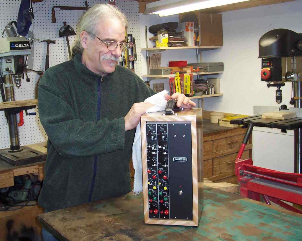
Tom Gruning with one of his Ward Beck ‘lunchboxes’

I came across Tom Gruning’s work on eBay and I was drawn to the level of craftsmanship that he put into these largely unheralded Ward Beck pieces.  What’s/Who’s a Ward Beck you say? Well,  today on Preservation Sound we will learn a little about Ward Beck, the Canadian broadcast-audio-equipment manufacturer; take a look at some of Gruning’s work reinvigorating and preserving these pieces for use in the modern music studio; and we will conduct a listening/recording test of his pieces in comparison with some studio-standards.

*************

*******

***
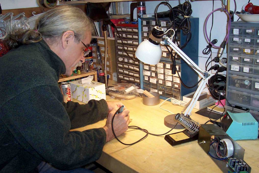
TG work in the Shop

PS: Tell us about Ward Beck, the audio-equipment manufacturer.

TG:  As far as WBS history…their consoles were/are broadcast consoles that were/are very, very high quality. I seem to recall reading that Neve was their primary competition in that market during the 1970s and ’80s. Neve moved over into recording consoles and WBS stayed with the broadcast market. There is a really wonderful on-going WBS history thread in the forum at the Ward Beck Preservation Society website. I suggest all your readers go there and tune in as it is an absolutely fascinating first person account of that history.

PS: How did you get involved with converting old Ward Beck console modules into stand-along ‘plug-and-play’ rack units?

TG: I got interested in WBS equipment about five years ago. I was putting together my personal ProTools project studio and simply couldn’t afford excellent quality store bought mic pre-amps. Being a research guy, I spent inordinate amounts of time reading what people had to say about any and all console strips. These were, after all, considerably cheaper to come by than the plug and play Neves, APIs, Chandlers, and on and on. The Ward Beck stuff sounded like the best of the bunch in that first and foremost, people thought they sounded excellent and were built like tanks. There was also a really knowledgeable and helpful community of folks willing to help newbies like me: that is, the gang at the Ward Beck Preservation Society.

As I wound up learning more about making these things work, I started investigating different modules when I could afford them. At this point I have 460s, 461s, 462 and 472 EQs, a 466 compressor, 470s, and 490s in my personal stash. Eventually I’ll add some 441s and a few others I have my eye on.

PS: Tell me about the mic preamps that you sent me.
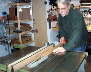
TG: The 49o pres I sent you started life as line level modules in a small, fourteen channel broadcast mixer. ….I pulled the first module and found the Hammond 6012 input transformer so I set about the task of turning these into mic-level units. It really didn’t take too much modification to turn them into mic level units and I wound up bypassing the logic circuitry in many of the racked pairs. Besides simplifying the signal path and eliminating the possibility of ICs crapping out, the mod (which I credit to legendary WBS guru Dave Thomas) gives the pre a pleasingly accentuated mid-range presence that really jumps out in a mix. They are great sounding pre-amps and prices on them are still very reasonable.

PS: Tell us about some of the different vintage Ward Beck pieces out there in the world.  What should folks look for?  What to avoid?

TG: I like the sound of all the WBS modules with input transformers. Bypassing the logic on the 490, the signal path is essentially the same as that of the 470. These sound really good on snare/high hat, electric guitars, and various other sources. The 460 series has a bunch of different designations: 460A; 460B; 460M; 460L,;460LA; etc. My favorites are the ‘L’ and ‘LA’ models simply because they are, as I recall, the most recent of the 460s and they have the really nice sealed pots, fully parametric EQ, and so forth. However, there really isn’t a hell of a lot of difference between the sound of an ‘A’ or ‘B’ and any of the others. The 460s have a big black custom made Hammond input transformer that really gives them a yummy, big, fat, round presence that is at the same time clear and nicely balanced. And they really are built like tanks. I’ve only run across two WBS modules that I couldn’t get up and running: a 466 compressor that I sent to Tristan Miller, a very talented Canadian tech who whipped it into shape, and a 461 mic-pre that I’m still banging on and eventually will get working. Most of the time, cleaning and radically exercising the switches, which are the only really weak link in the WBS chain, will get them passing signal.

PS: What Ward Beck ‘rack-conversions’ do you have available in-stock at present?

TG: I still have a few of the 490H rack boxes in stock (like the one I sent you). I also have a slanted front maple eight pack wired for six slightly modified 460 modules and two 470s. That one has a separate 1U rack mountable power supply. At present the box contains the two 470s, one 460L, and one 460LA. Oh yeah, I also have several 2U pairs of Yamaha PM1000 modules in my GruningAudioworks boxes. I have pictures of all these things on my website tomgruning.com. I also build custom-made hardwood cabinetry for WBS modules and various other things including exotic wood cabinets that house powered “picnic baskets” for API 500 series compatible modules.

Also, just as an aside: If any of your readers decide to rack up some WBS (or Auditronics, or PM1000) modules and would like some help, please feel free to contact me. In learning how to do these, I ran across a number of people who have been very helpful and generous with advice and instruction. If I can do the the same that would be good.

*************

*******

***
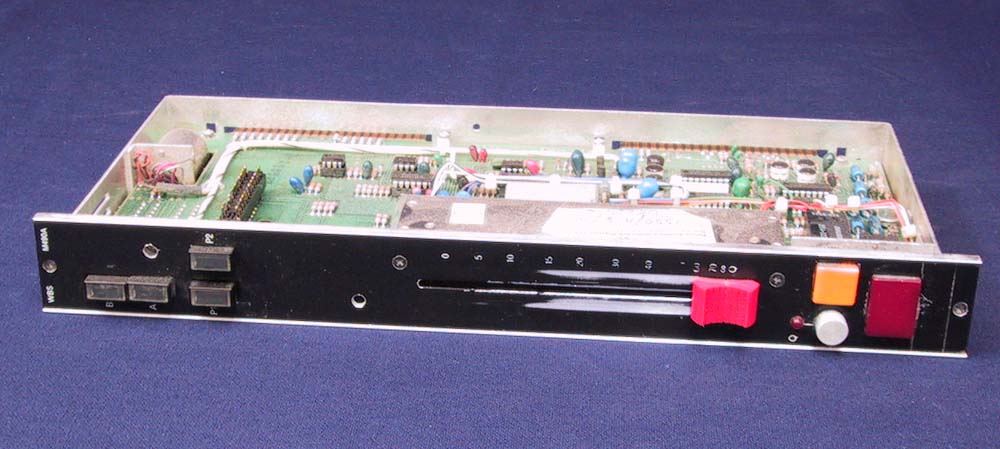
The Ward-Beck 490A input module in its ‘just-harvested’ state

(image source)

Alright.  Now on to the listening test.  TG sent me a pair of 490A modules which he had racked up, adding phantom power and system power in a very nicely fabricated black steel chassis.

I mounted them in a pre-amp rack at our new studio, Gold Coast Recorders (more on GCR to come…).    I have heard folks compare these Ward Beck preamps to API 512s.  I decided that this would make as good a comparison as any.  Especially since many of you are probably familiar with the sound of the API 512.

Our friend Tim W., recordist and drummer of the excellent band The Stepkids, came by GCR to help in this listening test.   Here’s what we did.  And it ain’t scientific.

Tim got behind a 20/14/12 circa ’64 ludwig kit that I had mic’d up with 4 mics:
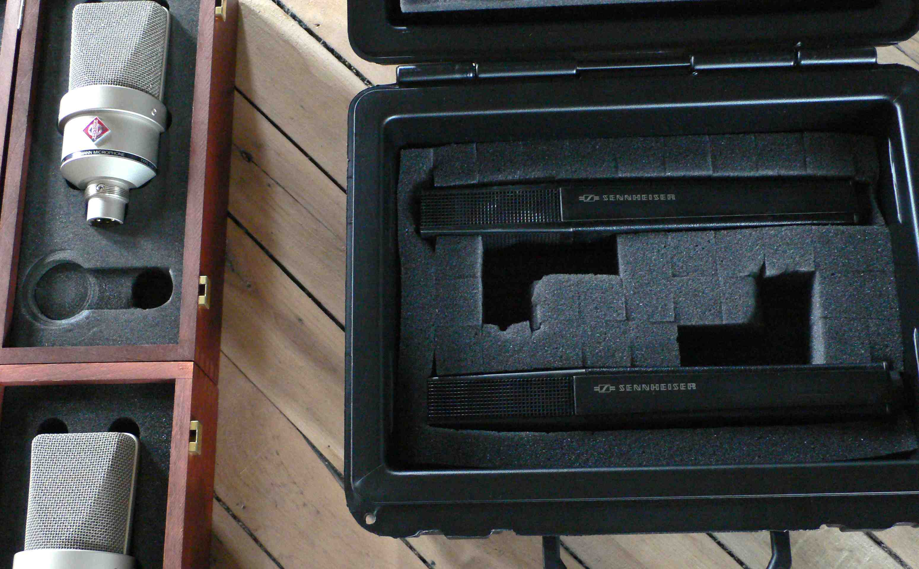
-two Sennheiser 441s on the kick, and two Neumann 103s in front of the kit.
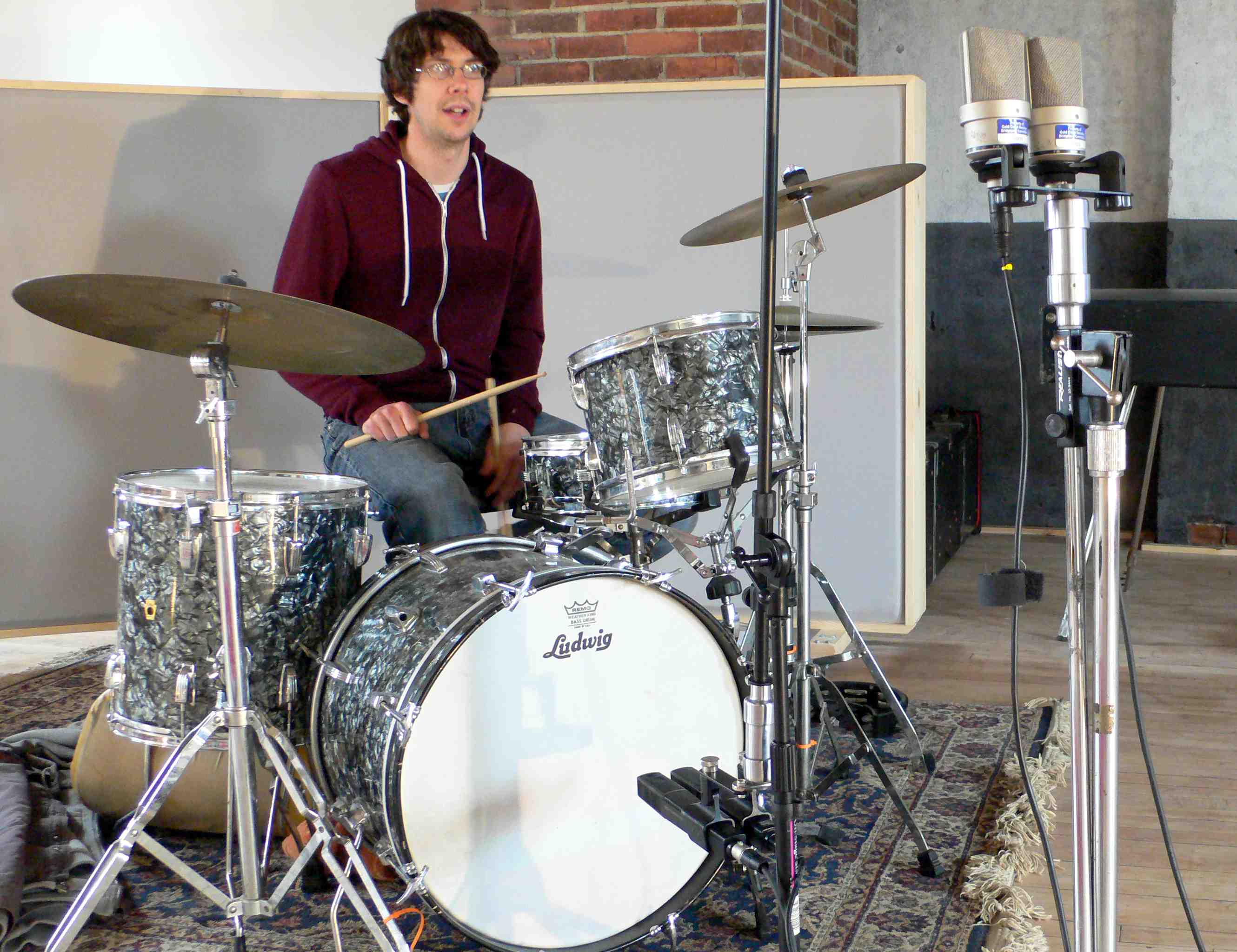
The mic pairs were spaced as close as possible.  One kick mic/Front mic pair went into the Tom Gruning-racked Ward Beck 490s; the other kick mic/front mic pair went into a pair of AP1 512s.  The outputs of the mic preamps went directly into pro tools.  no other processing was used, and the signals were played back and bounced with the faders at zero.

I asked Tim to play a beat inspired by this chestnut.  And here’s what we got.

Here is Tim’s performance as recorded thru the Ward Beck M490A pair:

LISTEN: WardBeck_M490A

…And as a reference, here is the exact same performance, recorded at the same peak level, but recorded thru the pair of API 512 preamps:

LISTEN: API_512

Here is a screen shot of the Pro Tools session.
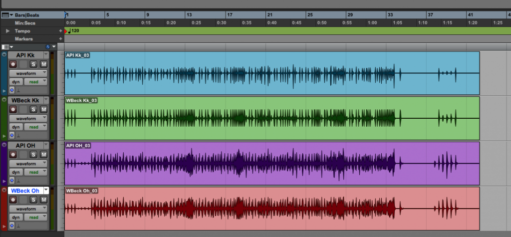
You can see clearly that the Ward Beck kick channel (Kk) is limited in comparison to the API kick channel.  It’s also more symmetrical.  The room mics (OH), on the other hand, have similar dynamic range except on the strong peaks.  Perhaps this greater dynamic range  was due to the fact I used the pads (on both the API and the Wbecks) for the room mics but not the kick mics.  In case you are wondering about phase: yes I did try reversing the phase relationships on both sets of mics, and i can confidently say that what you here in these mono bounces is the correct phase relationship.

Tim and I listened back in the control room at GCR.  The room is outfitted with a Blue Sky monitoring system with their 12″ sub; the low-end extension and clarity is very good.  And this was very helpful for this particular evaluation.

TIM W: ‘The signal from the Ward Becks really moves the room.  It’s much deeper in the bass but not as punchy (as the APIs).  I can really hear the articulation of the Toms in particular (with the WBecks).  There’s less presence of the hi-hats and the cymbals in general.  The bass is really deep – there’s more length to the kick drum sound.

PS: The APIs are a lot more focused, but there seems to be an entire octave of additional bass extension to the kick drum with the Ward Becks.  I feel like it is unusual to hear mic preamps that have this much ‘attitude’ but actually have deeper bass than a high-end preamp like an API.  The low mids feel scooped on the Ward Beck; the high extension is not as good.  I imagine the Ward Beck would be great on rock bass guitar or maybe room mics for a kit.

TW: The API is giving me more low mids in the snare and toms, but i am not hearing that real low end in the bass drum.  (the API pair) is more ‘punchy’ rather than really bassy’

*************

*******

***

I encourage you to listen to the audio examples above and draw your own conclusions.  I feel like the Ward Becks are good addition to the rack; I am definitely excited to try them on an SVT cabinet, and some loud rock vocals too.  It’s definitely a very coloured sound – both in terms of the compression and the scooped low-mids and slightly rolled-of highs.  I will also give em a go on kick drum for sure.   Check em’ out on Gruning’s site; you might be pleasantly surprised how affordable they are.
 

Categories
Guitar Equipment Technical

Magnasync Moviola URS as a guitar amp – UPDATE

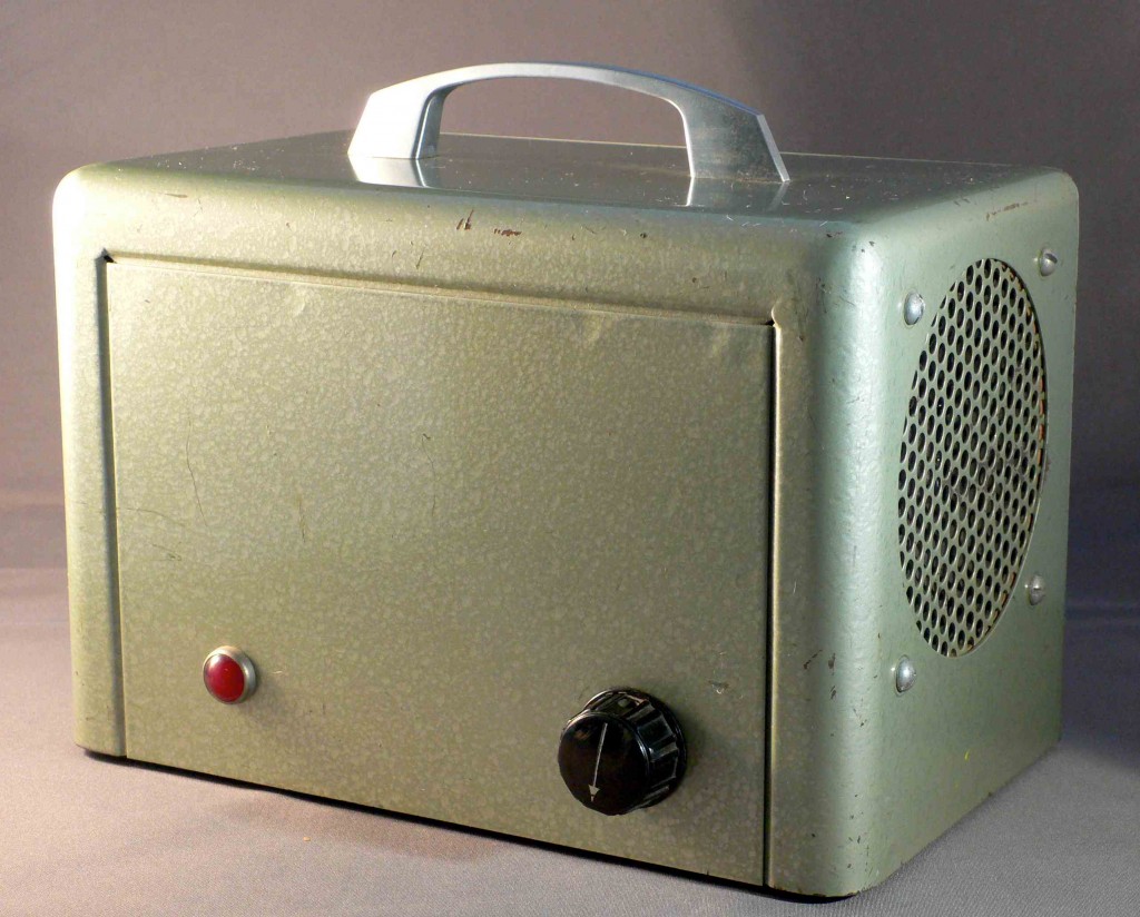
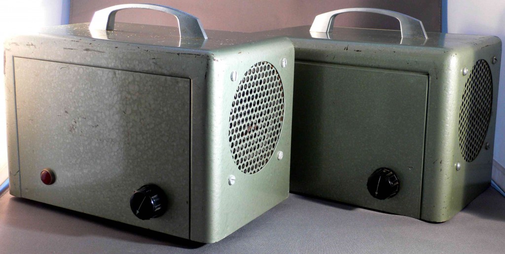
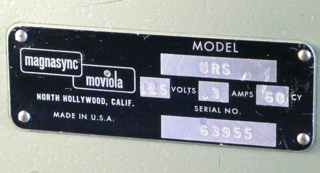
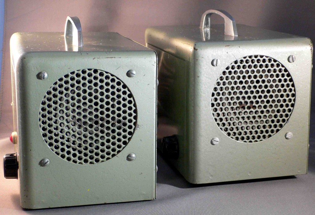
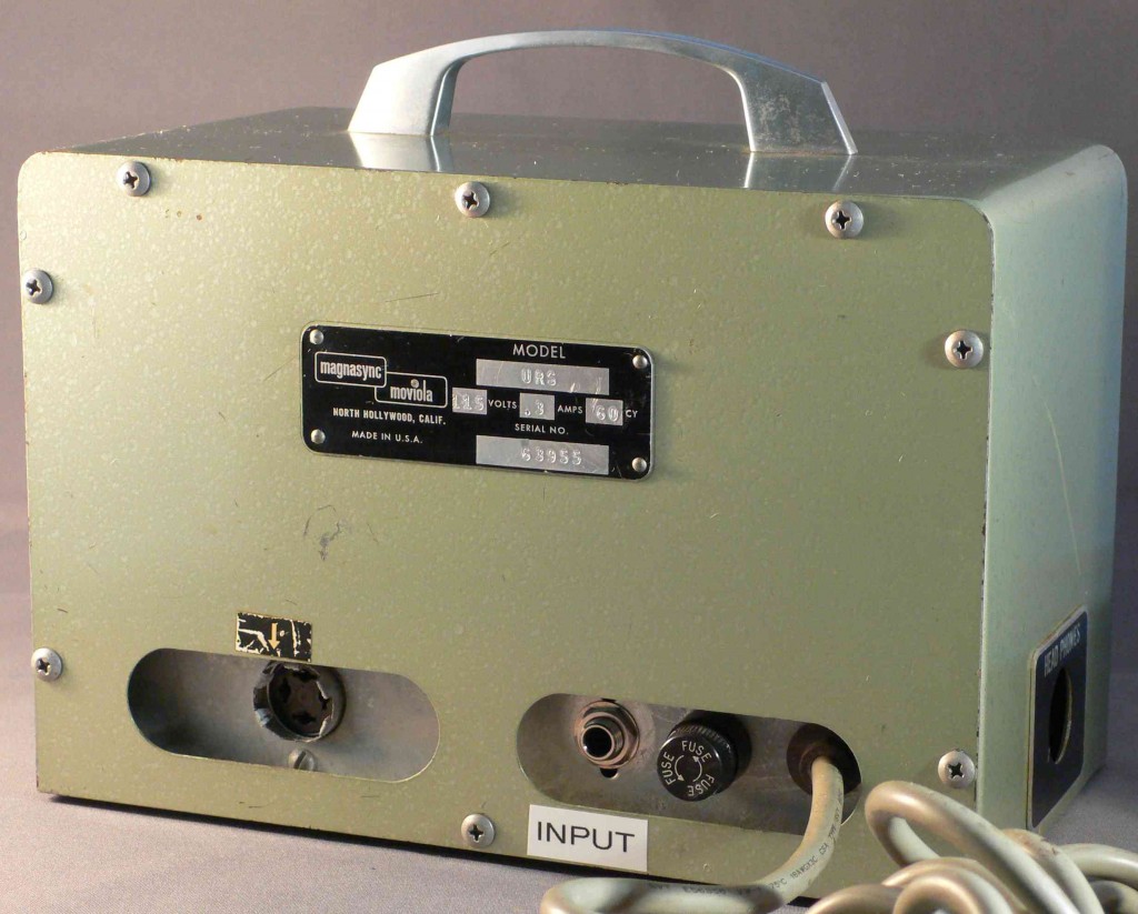
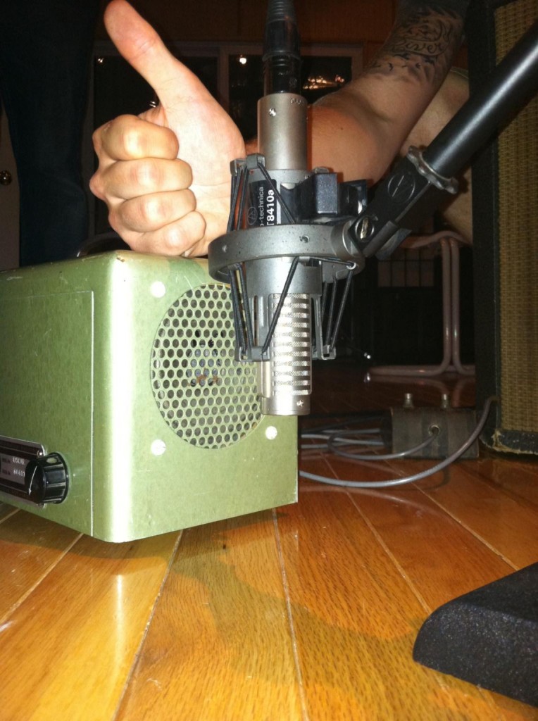
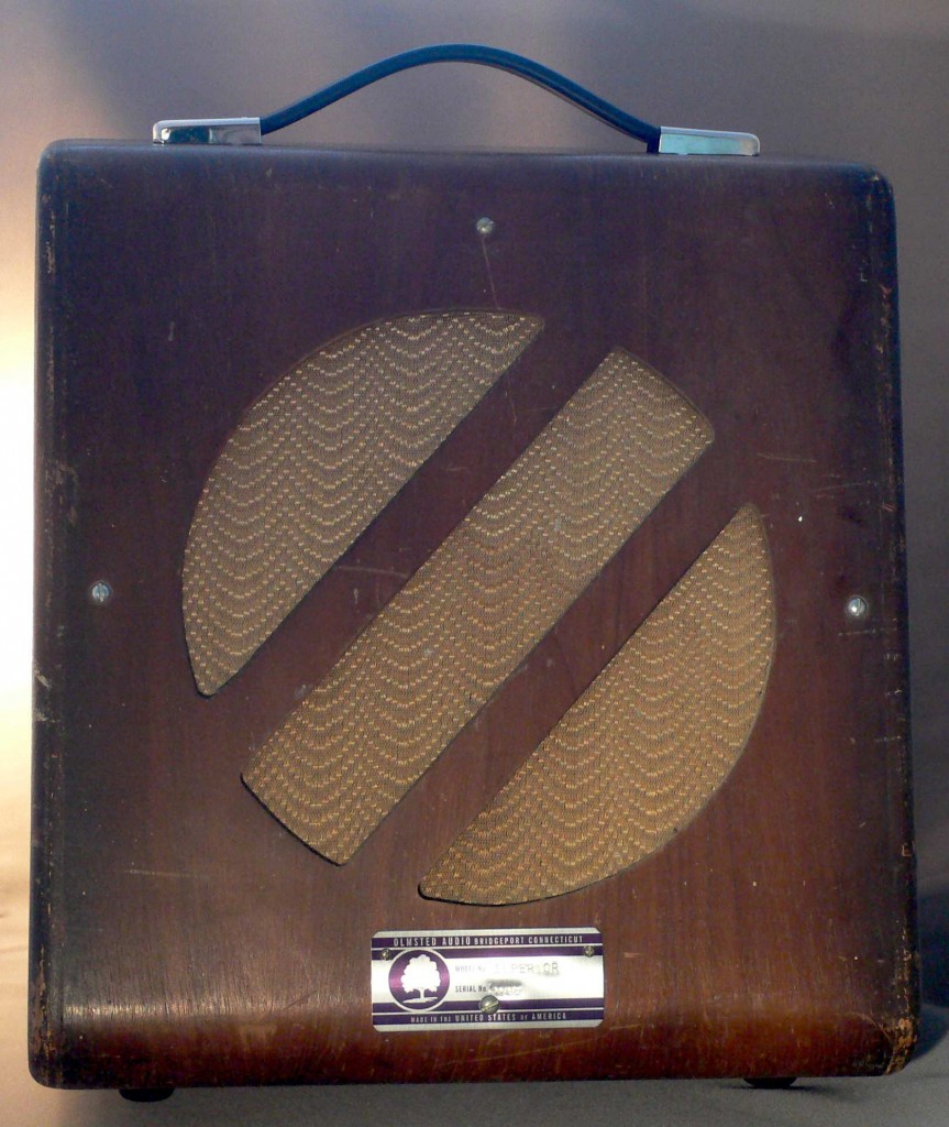
Magnasync/Moviola was a Los-Angeles based manufacturer of film editing equipment.  They did make a few audio products designed to support the large upright and flatbed Moviola film-editing machines which were their main products.   The most common of these audio-products is the URS 5-watt tube amplifier with built in 4″ AlNiCo speaker.  The URS apparently debuted sometime around 1955.

I recently purchased a pair of these things for a few bucks.  Aside from needing new pilot bulbs and some contact cleaner in the volume pot, they seemed to be working alright.

The rear of the unit (not shown) has a 1/4″ speaker jack (labeled ‘Headphones” which mutes the built in speaker when a cable is inserted.  Other than that, though, there was no obvious input jack.  There is a 4-pin amphenol jack with DC present on 3 of the pins.  the 4th pin is the audio input. Ahh Ok.    There is a also a single-pin DC power connector/takeoff?  Not sure.

Anyhow, kinda irrelevant.  Since no one is going to be using these things with an actual Moviola sound-head, figured I would just make em into lil guitar amps. OK it’s gonna get a little technical here, so pls skip the next paragraph if you wanna just get to the sounds…

Since the tube compliment is 7025 (aka 12AX7) – into 6AQ5 power tube (aka basically lower-voltage rated, small-bottle 6V6) with a single volume pot between the two 7025 stages, this thing is basically…. a tweed fender champ.  Yes, there are some important differences – different plate resistor values, no cathode bypass caps on the preamp stages, and i think some frequency compensation in a the feedback loop?  But basically a tweed champ.  ANYhow…  Following the advice offered here, i put a 1/4″ guitar jack where the single-pin power socket had been.    Then i simply added the other basic components of a Fender guitar-input-stage:  a 1m resistor to ground, and a 68k resistor between the input and the grid of the input tube stage.  Replaced the 2-wire AC cable with a 3-wire grounded cable, and done.

There is plenty of talk on the web about these things…  lotsa folks have converted these to guitar amps in the same manner that i discussed… and people seem to be very happy with them.    Check out this fellow’s work. He did an especially thorough job.  I was personally kinda shocked with the sound that it makes.  Never in my life have i heard so much distortion and fuzz out of an amp.  It really is, pardon my language, fucking insane. Here’s 3 sound clips.  (Gibson Firebird gtr.   SM57 3″ in front of the speaker, into MBox.  ‘Clean’ and ‘Overdrive’ examples have analog echo pedal between the guitar and the amp.  Fuzz is just the amp.  No other eq or processing applied).  Check it…
Clean: Magnasync_URS_clean

Overdrive, fingerpicked: Magnasync_URS_overdriven

Fuzzed out (max volume): Magnasync_URS_fuzz

*************

*******

***

UPDATE:  One of the two URS conversions that I built was purchased by producer P.K.  for use on an album project with a new band out of London.  When the record comes out (assuming the URS tracks make the final mix), I’ll post links to the cuts here so that y’all can hear the sound of these fantastic little amps in-context.
Oh and about that other URS conversion that I built: as of today, it is still on-sale at Main Drag Music in Brooklyn NY for a mere $250.  Call or email them if yr interested.


Categories
Custom Fabrication Technical

Recent Custom-Build Stereo Amplifier (Home Use)

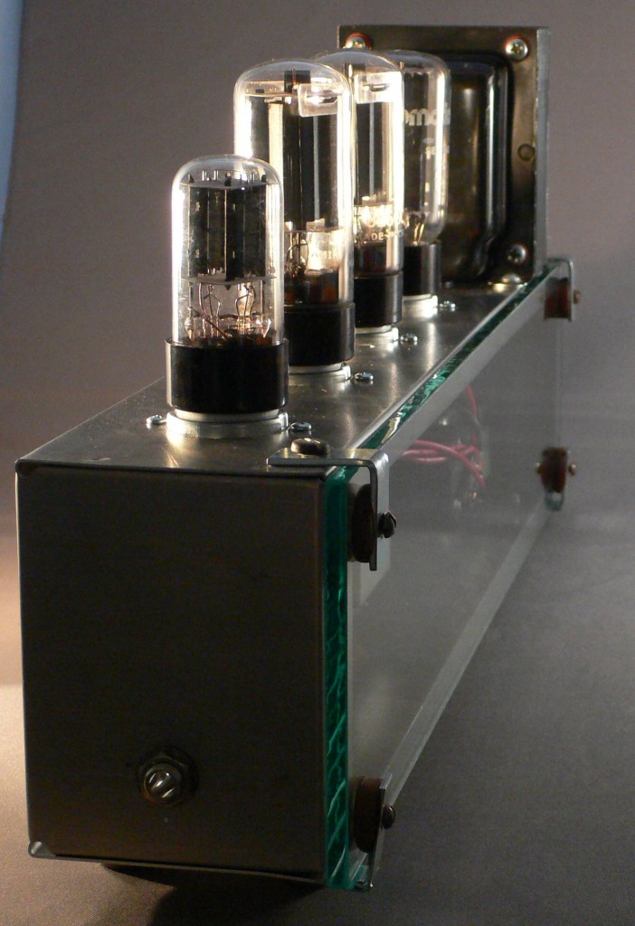
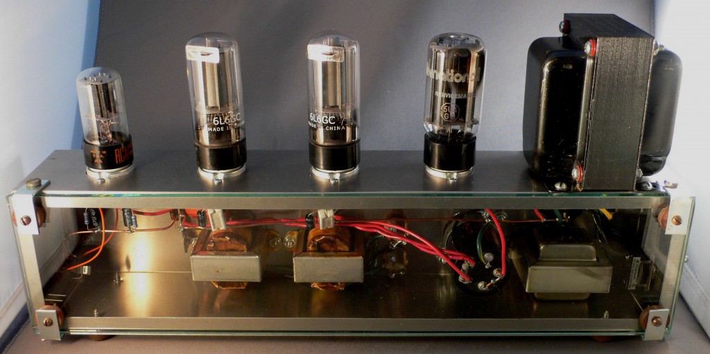
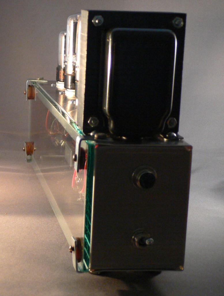
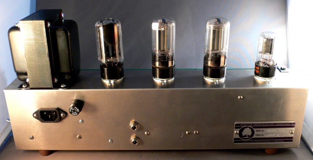
Above: a very minimal single-ended stereo amplifier with very low gain, designed to accept headphone-level input from an iPod or Laptop and drive a pair of loudspeakers.

The circuit design is extremely simple – Each 1/2 of a 6SN7 feeds the grid of a 6L6 through a .1uf capacitor.  There is a 3-stage power supply with a choke filter before the B+ hits the output transformer.   I have built a couple dozen of these, and the design works well – the sound is very clean and direct; the small 8w output transformers do roll off the very low end, but I have never found this to be an issue with the music that I listen to.   Easy to add a powered sub to the system if one was into rap or heavy orchestral music. BTW, I use this very same circuit, with the same components, for music listening at home; I have mine connected to the output of an Airport Express, powering a pair of Bose 201 speakers. For instances when customers have wanted to hook the unit up to a line-level (rather than headphone-level) output, I substitute a 6SL7 for the 6SN7.  This requires simply changing the cathode resistors on the input tube socket and gives 3x the voltage gain.

What interests me in this design is not the mundane circuit – it is the overall appearance/sculptural aspect of the unit.  I arrived at this particular form through consideration of the appearance of the vacuum tube; as much as possible, I have tried to make the overall complete unit an amplified echo of the tube itself.  The circuit is laid out extremely carefully and the components/wires color-coded (red for B+, orange for audio), green for grounds); it’s my perhaps naive hope that someone unfamiliar with audio circuits could look at/into this piece and maybe gain some understanding of the way that a tube audio amplifier works.

Categories
Technical

Tubes vs. Transistors in Recording Equipment

“Engineers and musicians have long debated the question of tube sound versus transistor sound.”

From the AES Journal, in the form of a paper first presented in 1972, Russell Hamm delivers a quasi-scientific study and analysis of the difference between tube and solid-state microphone pre-amps.  Click here to read the fourteen-page article. This paper confirms what most recording engineers seem to realize intuitively: solid-state and vacuum tube amplifiers operate equally ‘well’ (read: musically-pleasing) when operated totally clean.  However, Hamm reports that tube microphone pre-amps offer 15 – 20 db more acceptable semi-distorted headroom on transients, while only showing a 2-4 db actual increase in electrical output over this range.  I.E., as Hamm states, tube microphone pre-amps can be extremely effective compressors.  There’s more to it than that; read the piece and draw your own conclusions.


Categories
Technical

Simple Tube Program EQ project

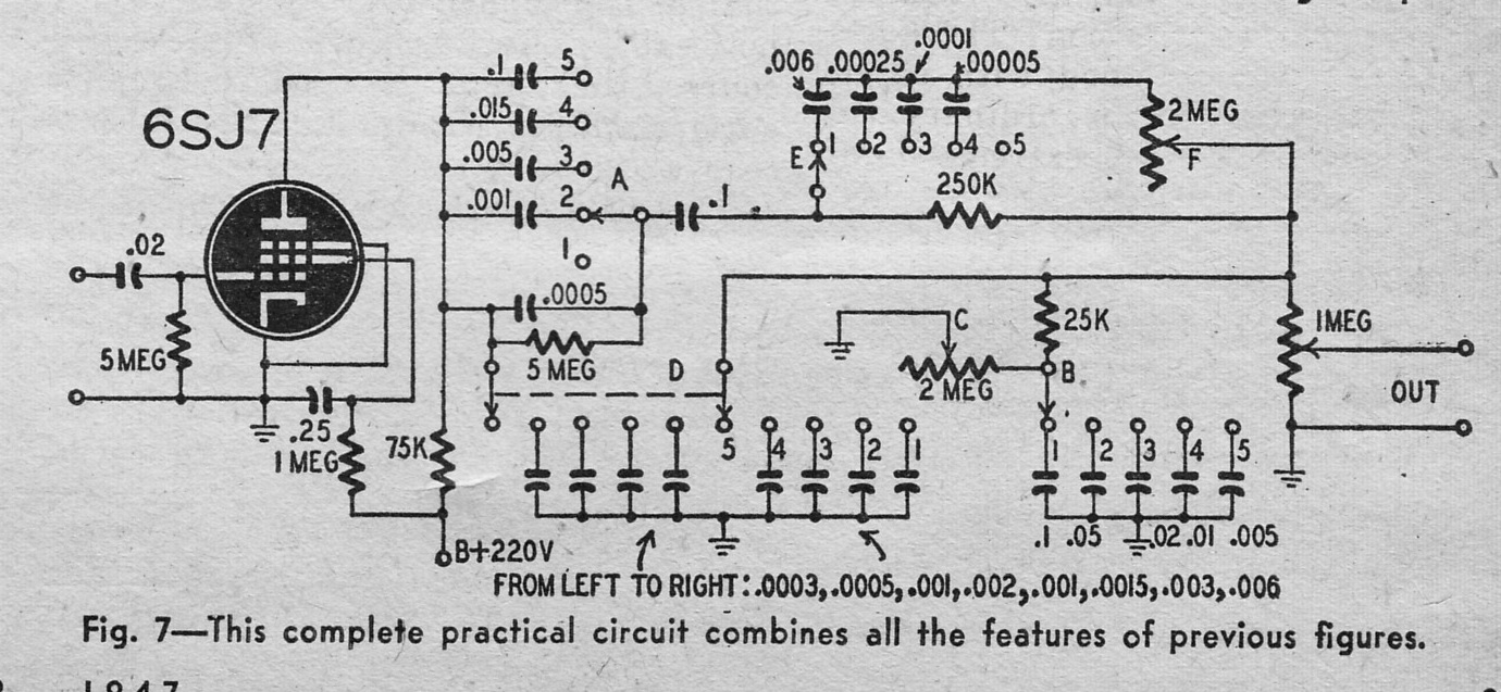
From the September 1947 issue of RADIOCRAFT magazine: an interesting ‘response equalizer’ project that looks to have great potential for use in the recording studio.  Download the complete article with schematics:

DOWNLOAD: ResponseEQ1947

You will need to download and read the article for complete details, but essentially this circuit provides the following functionality, with 7 controls:  4-position high-pass.; variable low-end boost with 4 selectable frequencies; 4-position low pass; variable high-end boost with 4 selectable frequencies; 10db overall gain with variable output trim.  And it does all of this with no inductors or transformers, and just one very cheap 6SJ7 tube.

To use this circuit in a complete studio-ready device, we will need to add several things:  First, an output stage capable of easily driving a 15k:600 output transformer.  I am going to try the very simple output circuit show above, taken from tubecad.com.

A 250-300v DC power supply (plus 6.3v filament power) will also be necessary; plus input and output transformers.  Once I get this all together, I will also need to figure out a good, silent bypass-switching arrangement.   Should be a good inexpensive tube eq project.   The overall application is very similar to the Pultec EQP-1A; this unit will not have as precise control due to the lack of inductors; but it will cost a heck of a lot less (likely $250 of parts verses $800 to build a Pultec).  Plus it allows one to boost and cut at different frequencies, which the Pultec does not offer.  Expect some build-notes, images, and audio examples here soon.

Categories
Technical

Gately EM-7 Mixer and EQ-7 4-channel Equalizer Unit

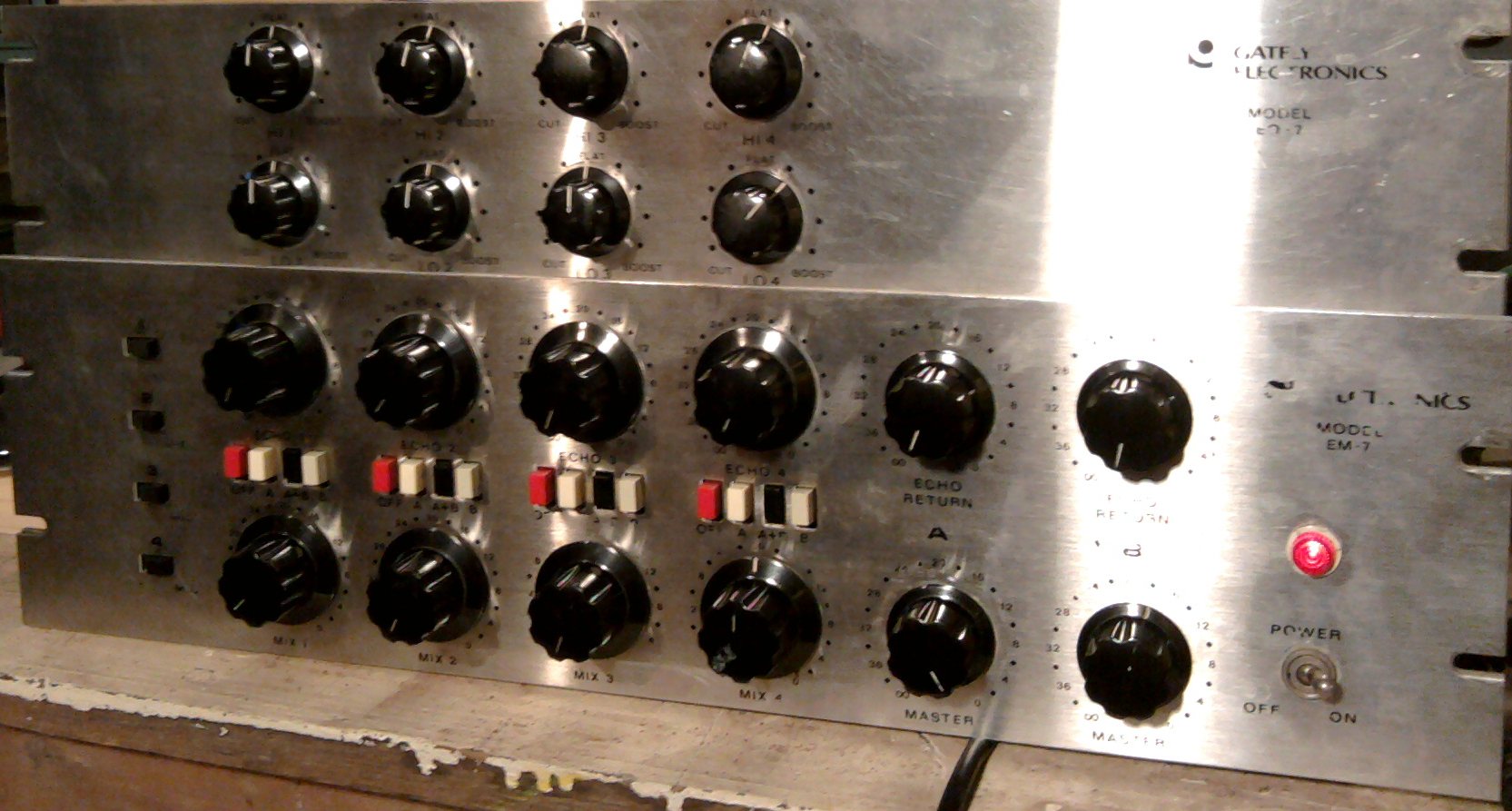
In a previous post, I included the scan at left from a 1969 issue of the AES journal.  It’s an ad for the Gately Electronics EM-7 4×2 mixer and EM-7 4-channel equalizer.  At the time I had hoped to find one of these little setups, and sure enough,  one of the EM-7 mixers came along on eBay.  I checked the sellers ‘completed listings’ and saw that he had sold the companion EQ-7 equalizer unit earlier.  I contacted that buyer through eBay, indicating that I was interested in the EQ-7 should he decide to part with it.  Sure enough, he did.  So I was able to get an EQ7 as well.

All in all it turned out to be a great deal.  It was a bit of a pain in the ass to get these things working, but at the end of the day I ended up with 4 fully discrete mic preamps with discrete EQs, all running on 48v, and all with UTC input and output transformers.

This post will get a bit technical, so follow the link below to read on…  CLICK TO CONTINUE….

Categories
Guitar Equipment Technical

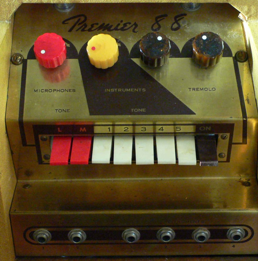
Premier 88: ready to go.

After probably 14 hours of work and $200 of parts, my Premier 88 is working 100%.

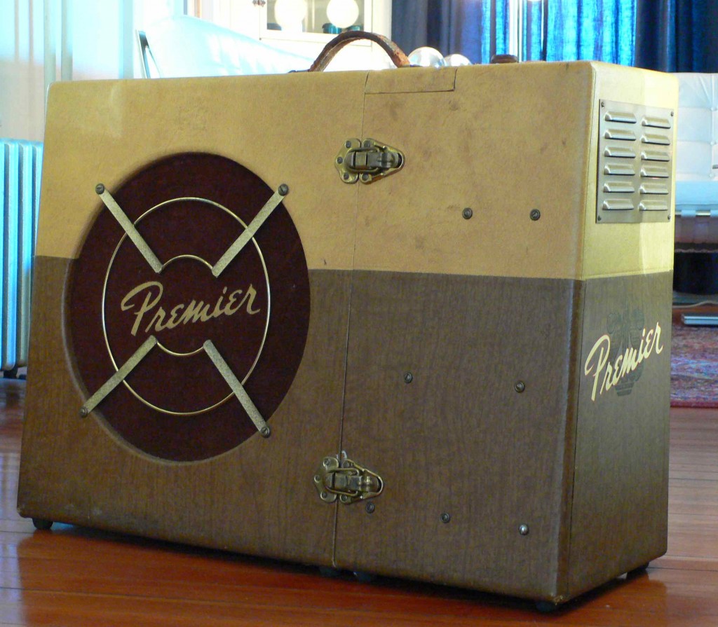
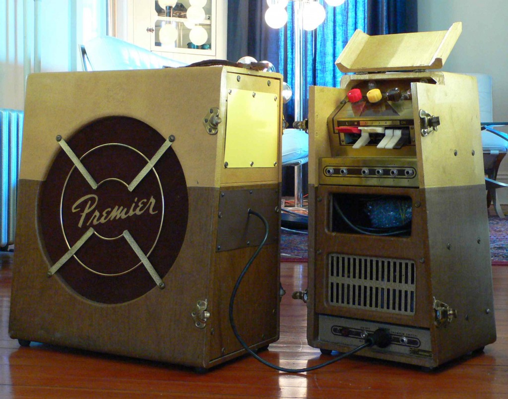
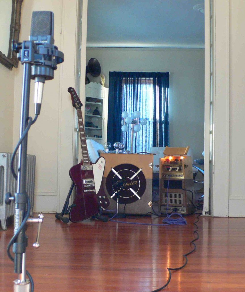
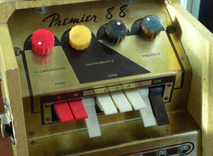
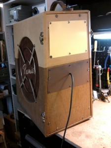
As I described in an earlier post, the Premier 88 is a rare and highly unusual instrument amplifier from the 1950s.  It consists of an amplifier unit and a speaker unit; but rather than the amplifier unit sitting atop the speaker, like most every other 2-piece amp, the 88’s amplifier sits beside the speaker cabinet.  The two sections clasp together with luggage latches.  It moves as one (very large and heavy) piece.

This odd side-by-side form-factor is not the only unique feature of the 88.  Check out the control panel.  Rather than conventional bass/middle/treble knobs, the ‘instrument’ channel of the 88 has 5 organ-stop-type levers that can be switched in or out.  Each lever is a bandpass filter.  IE., if you depress all 5 levers, you get the full tonal spectrum.  If you depress none of the levers, you get silence.   The ‘Microphone’ channel also has a pair of unusual tone control switches; they seem to be hi-cut filters.

Here are some examples of the sounds that the 88 produces.  Right channel is an SM-57 close to the speaker; Left channel is a 414 in omni approx 10 feet away.

LISTEN:  Low_and_High

Listen: Mid_only

The trem is super weird and extreme. Here are a couple of examples:

Listen: Trem_low_settings

Listen: Trem_HighSpeed

***********

*******

*****

**

In all honesty, this amp was a pain in the ass to service.  When I first brought it into the shop, it did turn on and pass signal; the tremolo sort-of worked, as did all of the tone controls.  It just sounded terrible and it had no output.  The longer it ran, though, more and more parts seemed to fail, starting with B+ resistors and then moving on to the 50 year-old tubes.  So eventually I ended up replacing most of the components in the amplifier.

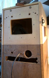
When I first opened it up, I saw tha someone had added a Pilotuner mono FM receiver to the speaker cabinet.  I removed the tuner, and I then had to fabricate cover-plates for where the tuner face and tuner knobs had been.  I used aluminum plate stock.  That was the first piece of work.  And then:

*replaced the 15″ Jensen Alnico speaker with a new Jensen 15″ ceramic (there was a weird rattle in original speaker)

*replaced all electrolytic capacitors in amp (approx. 20)

*replaced all B+ and plate-mixing resistors in upper preamp chassis (approx 15)

*replaced all caps in tremolo circuit (some needed to be replaced twice in order to get the right response)

*clean all tube sockets and replace 3x 12ax7 in pre-amp.

*add grounded AC line to power amp chassis

*replaced 6L6 and 5U4 and 12au7 tubes in power amp chassis

Good lord.  Was it worth is?  Who knows.  Once you start a restoration like this, you kinda just need to push on through until it’s done done done.  This is possibly the only working example of this amp in the world, so I felt like it deserved a chance.

The repair was difficult owing to 2 conditions:

*There is no schematic available for this particular iteration of the Premier 88, and the pre-amp is extremely complex owing to the bandpass filter arrangement.

*The amplifier is split into 2 sections: The top half is the pre-amp and trem circuit, and the bottom half is the phase inverter, power amp, and power supply.  These two sections are joined by two cables: a shielded RCA line (audio signal) as well as an octal snake that carries B+, ground, heater lines, and tremolo defeat control.  Owing to the extremely short length of these two cables and the manner in which they pass through the tight trapezoidal enclosure,  the preamp cannot be operated unless the unit is fully assembled.  So… the preamp circuit cannot be operated while its circuit is accessible.

Now that all is said and done, it is clear that I would have benefited from making an octal extender cable so that the preamp circuit could be accessible while active.  Hindsight is of course 20/20.

A few things other repair tips that this repair has illustrated:

*If you are missing a schematic:  don’t assume that the plate resistors for 12A_7s are 100k ohm.  The 88 had 270k ohm plate resistors.  Generally speaking, when i get an old, noisy amp, I just replace all the 100k resistors, assuming that these are the plate resistors.  Bad carbon-comp plate resistors are often the source of weird intermittent noise in guitar amps.  But not in this case!  Premier used 270k ohm.

*Alnico speakers definitely sound better than ceramics for old guitar amps.  I always suspected this, and now I am convinced.  Wish I had sprung for the extra $100 for the Alnico Jensen.

*Don’t assume that working tubes can’t be causing weird intermittent problems.  I am generally pretty trusting of working preamp and rectifier tubes, and  I am often quick to assume that B+ resistors are bad, when i fact, it COULD also be the tube…


Categories
Publications Technical

MJ Audio Technology Magazine

In a previous post, I discussed the late great American magazine Audio, published between 1947 and 2000.  Audio combined equipment reviews, listening tests, music reviews, and DIY tech into a single publication.  It’s cessation has left a great absence in the American audio-scene that the internet has luckily filled (chicken or egg?).

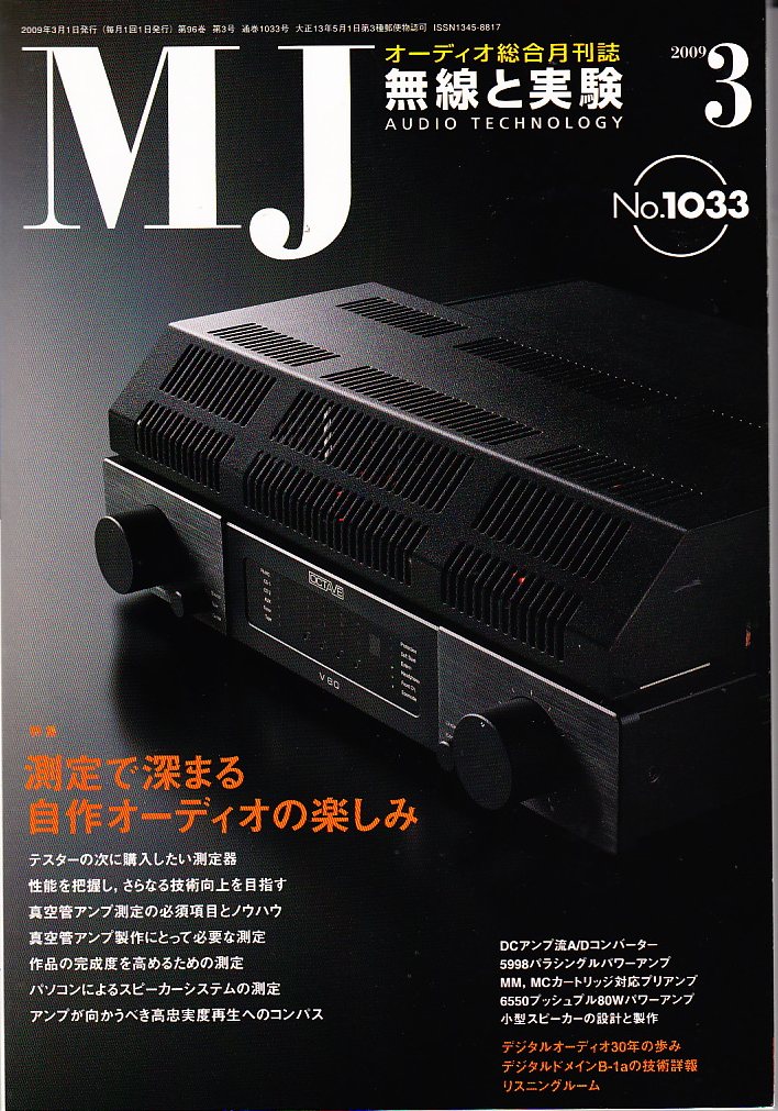
MJ Audio Technology magazine is the closest Japanese equivalent to Audio.   However, MJ has been in print since 1924 (!) and it is still being published.  Amazing.  Here is a brief history of MJ, taken from the DIYaudio listserve (member tiefbassuebertr):

“This magazine, founded in 1924 by Mr. Mitsugu Tomabeji, is one of the earliest and most influential radio magazines that I know. In the early years it was Radio experimenter’s magazine (Musen to Jikken = Radio and Experiments). The early publisher of this magazine was the currently brand ITO and the currently publisher now is Mr. Seibundo Shinkosha. In general this magazine is a DIYer magazine and is very technical but is full of great articles on electronics and speaker design, room acoustics, audio history, as well as reviews, news, show reports, etc.”

(Web Source)

Even if you can’t read a word of Japanese, this is a great magazine to pick up if you are interested in audio DIY at all.  Recent issues can be purchased at Kinokuniya in New York City.  I would bet that the several Kinokuniyas on the west coast stock it as well.

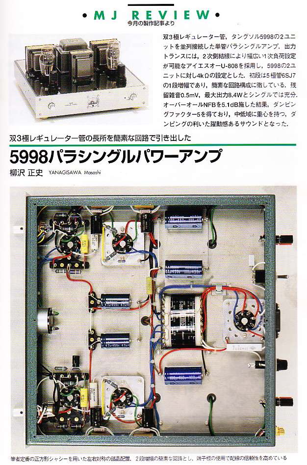
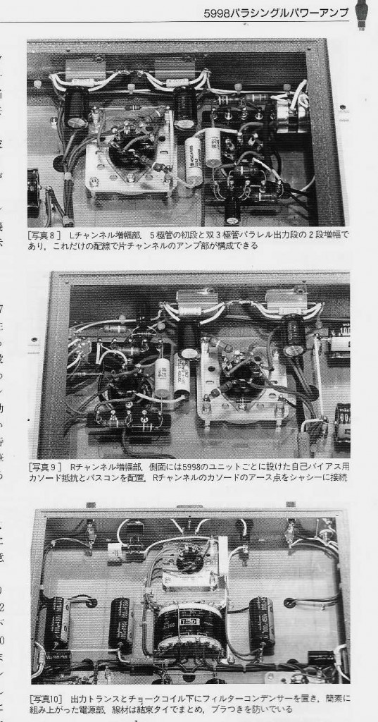
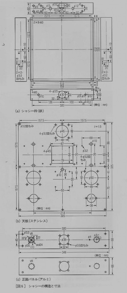
Here is an example of a project from the 1033rd issue.

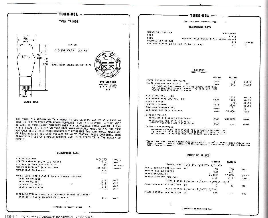
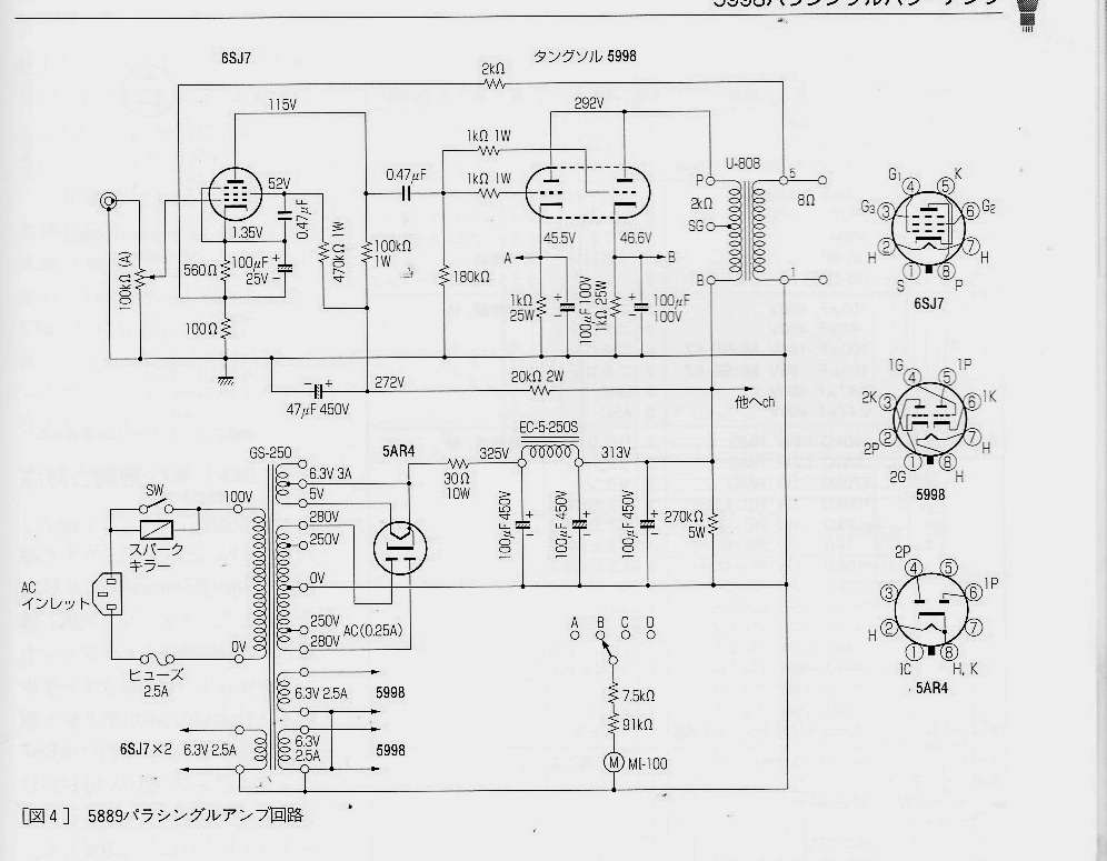
…Here we see a beautiful build of a Single-Ended parallel stereo amp which uses the very unusual 5998 twin-triode tube.  This is a tube that I had not been aware of, as it was never intended as an audio tube by the manufacturer.  Nonetheless, MJ has based this project around it.  We are offered the tube data sheet…

A very clear and well-illustrated schematic,…

…Layout details,…

…And even chassis-fabrication guides.

Overall, the level of quality and attention-to-detail most reminds me of the old Mullard “Tube Circuits For Audio” book (also excellent).   Finally, the technical performance specs, and listening tests. These listening tests generally seem to involve the singing and/or playing of pretty-yet-demure women.

This project is given much greater detail in the magazine than I am providing here, and in fact it is only one of several on offer in this issue alone.  Check it out if you can.

Categories
Custom Fabrication Guitar Equipment Technical

The Field-Coil Guitar Amplifier

(web source)

The year is 1946.  You are a man of the world.  Bold and sophisticated.  A true musical connoisseur.

(Web Source)

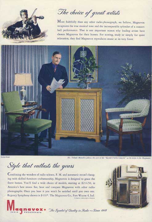
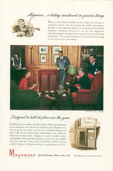
In your stately home you use music to relax and to entertain.  Your Magnavox Regency 155 combination Radio/Phonograph, with state-of-the-art dual 12″ speakers,  serves you well for many decades.  After many long and fruitful years, the day will come that you will pass into the next life; and then I will build a guitar amp from your Enormous Radio.

*************

******

***

When I did in fact purchase this gigantic ‘Instrument,’ as the manual called it, it was far too large to fit in my car.  So with some basic hand-tools I dissected my $25 dollar purchase in the faded parlor where it had sat for a lifetime.  I removed the radio chassis (mostly junk save for some 6J5 tubes), the later-added GE RIAA phono pre (sold on eBay), the 25 watt amplifier chassis (salvaged the tubes, output and phase-inverter transformers), and two 12″ Magnavox field-coil speakers.

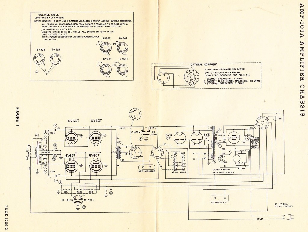
Luckily, my purchase came complete with all the manuals, service guides, and original warranty card.  Using the schematic I was able to see how the ‘field-coil’ speakers function in this type of amplifier.

In my previous post on field coil speakers, I went into some detail about this technology and its relationship to more modern speakers.  Now the time had come to actually build a working audio device using this antique technology.

I have completed the piece, and in this article I will describe some of the challenges faced, techniques used, and offer some audio examples of the end result.  This is a somewhat long article, so if you just want to hear the audio, skip to the end…

FOLLOW THE LINK BELOW TO READ ON….