I play the keyboards.
Images of Rock n Roll Keyboard players circa the mid 1970s.
 Alright! So earlier this week I described the successful completion of the RCA OP-6/BA-2 microphone preamp. Check out this previous post for all the construction and technical details. The short story is: the RCA OP-6 is one of the most fetishized vintage mic preamps out there; I have always wanted to try one out; the easiest/cheapest way for me to do this was to build one (or at least as close as I could get). The problem is that the input stage requires a special attenuator device, exact values unknown; therefore I had to substitute an input stage from another device. I chose the input stage from the RCA BA-2, as I have built many of these and they always work great. The result: a hybrid of the OP-6 and the BA-2.
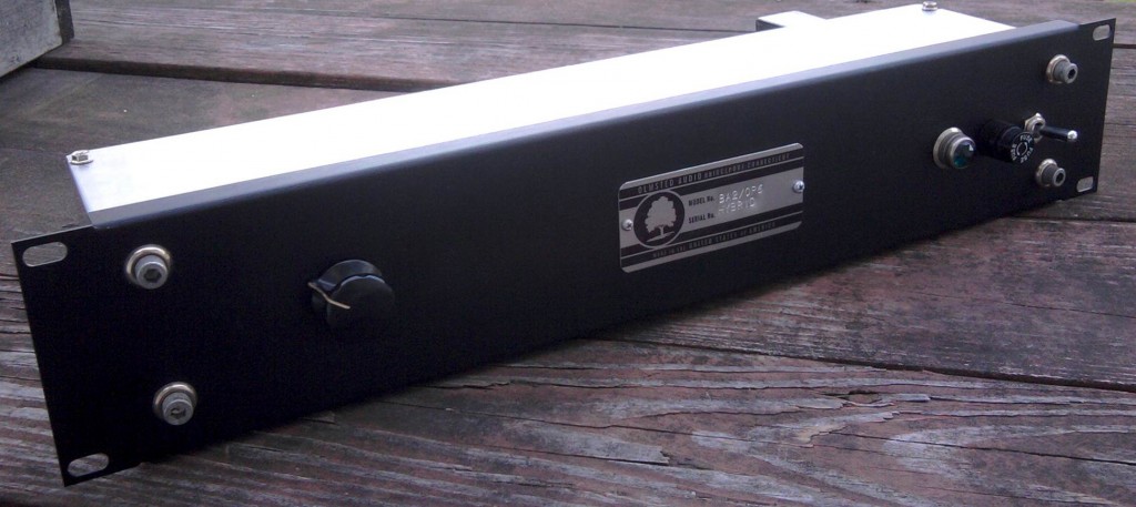 OK so there it is. Anyway, the very helpful+generous TW came by to help me out on this one. I wanted to try the OP-6/BA-2 Hybrid (hf. OBH) on a couple of different sources with a couple different types of mics. We a/b’d the OBH with an API 512. I use the API 512 as a benchmark for mic-pre shootouts because it’s a high-quality unit that many people own and use regularly. What you are about to hear are identical mics tracked through the two different preamps, direct to Pro Tools via a Lynx Aurora. Levels were matched. No other processing, level adjustment, or manipulation was done. You are hearing exactly what came out of the preamps. To appreciate the differences between the units, you will need to listen to these files on good headphones or a full-range speaker system. If you listen on a system with a subwoofer (we used the Blue Sky system at Gold Cost Recorders), you will hear some dramatic differences.
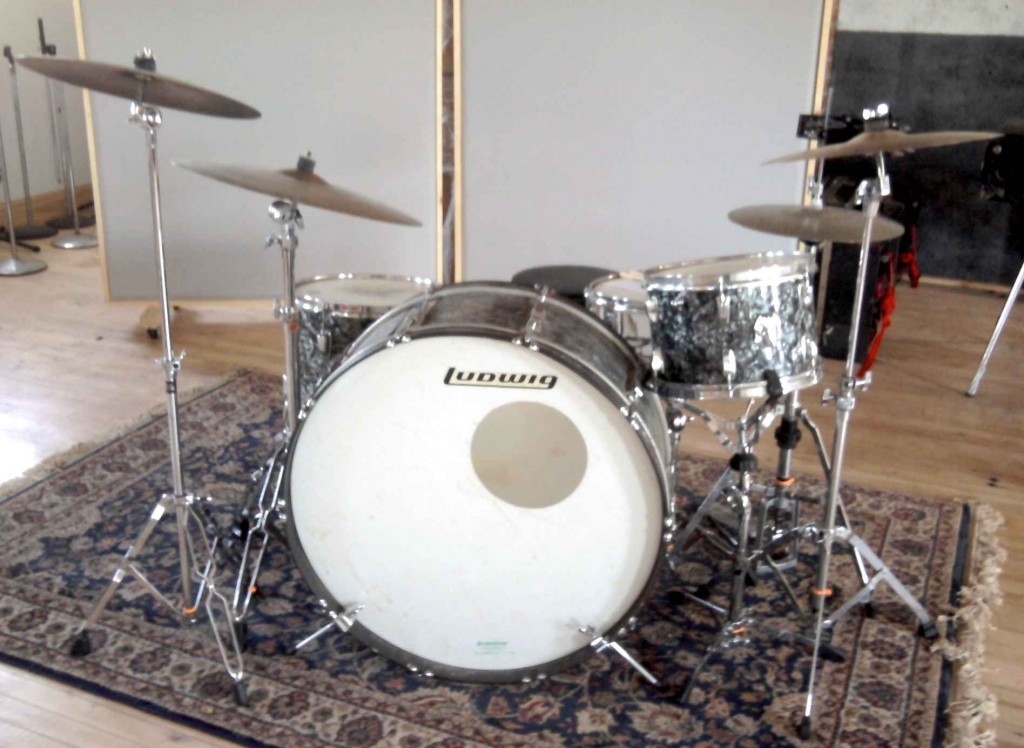 OK. So first up: let’s listen to the drum kit above. These are vintage ludwig drums, 30″ kick, 12″ and 14″ toms, 14×5 wood snare. Cymbals are fairly dark old Zildjans. You are hearing two identical Shure SM-81s placed right next to each other, approx 8 feet in front of the kit, pointed directly at the kit. The 10db pads on the SM81s are engaged. The SM81 is not the prettiest sounding mic, but they have a very flat frequency response.
First: here’s the API 512:
LISTEN: Drums_API
…and here’s the OBH:
LISTEN: Drums_RCA_hybrid
Our impressions were as follows: the OBH has more low end extension. On the Blue Sky system, the kick drum in the OBH signal moved the room in a way that the API simply could not. The API seemed to move the kit a little closer to the plane of the speakers, but at the same time the top end was not as in-focus. There is a definite low-midrange boost going on with the API. I can say this with relative confidence because I measured the frequency response of the OBH and it is totally flat from 15Hz – 10K, with only a very slight raise above 10K. In terms of operation: the API gain control was at 3 o’clock; the OBH was at 9 o’clock. WOW that is a lot of gain.
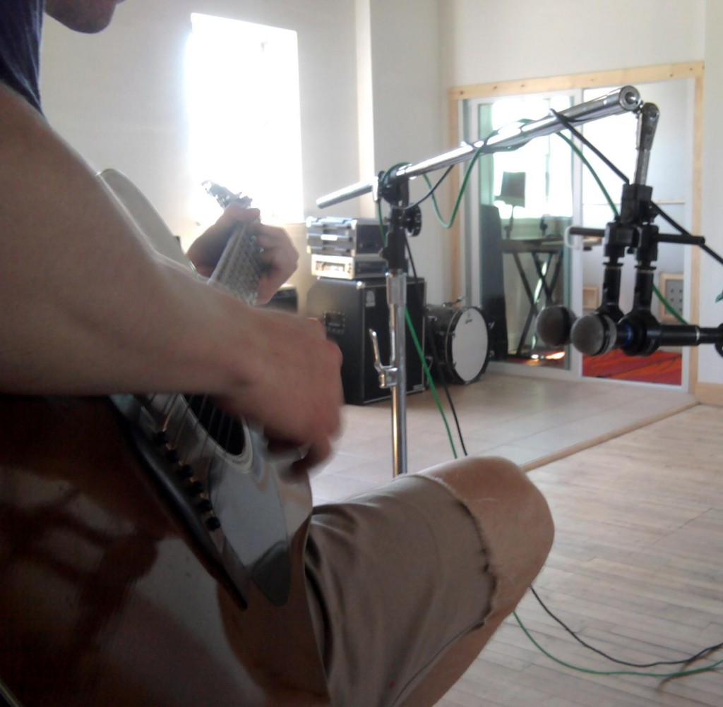 Next, let’s listen to some acoustic guitar. TW played an old Martin D-19 (same as a D-18) that i mic’d with a well-matched old pair of Beyer M260s ribbon mics. The M260 has a built-in gentle roll off that starts at around 200hz
 Alright so take a listen. First, the API 512:
LISTEN: AcGtr_API
…and now the OBH:
LISTEN: AcGtr_RCA_Hybrid
Our impressions were that the OBH had more low bass but less low mids; it had a more ‘mellow’ feeling. The OBH also had better high-end extension. This also resulted in slightly more HVAC (air conditioning) room noise in the OBH. Although I like the sound of the OBH again here, it is less of a clear-cut choice. The mid-boost that API seems to deliver is very welcome in this particular setup.
In summary: TW put it this way: ‘(the OBH) is like a pair of gentle shelves (shelving EQs) on the very highs a lows.’ I think this is very accurate. The OBH seems to give what I think of as an English sound: that sort of larger-than-life, hyper-real sound that UK records have always aspired to. I highly encourage your DIY’ers out there to give this project a shot; you will find it to be a very useful tool.
Thanks again to TW for his help with this listening test; T’s band THE STEPKIDS is just back from LA where they did a direct-to-vinyl (!) live set in front of a studio audience (!!!) at Capsule Mastering Labs. Check out the details of this very cool endeavor here and here.
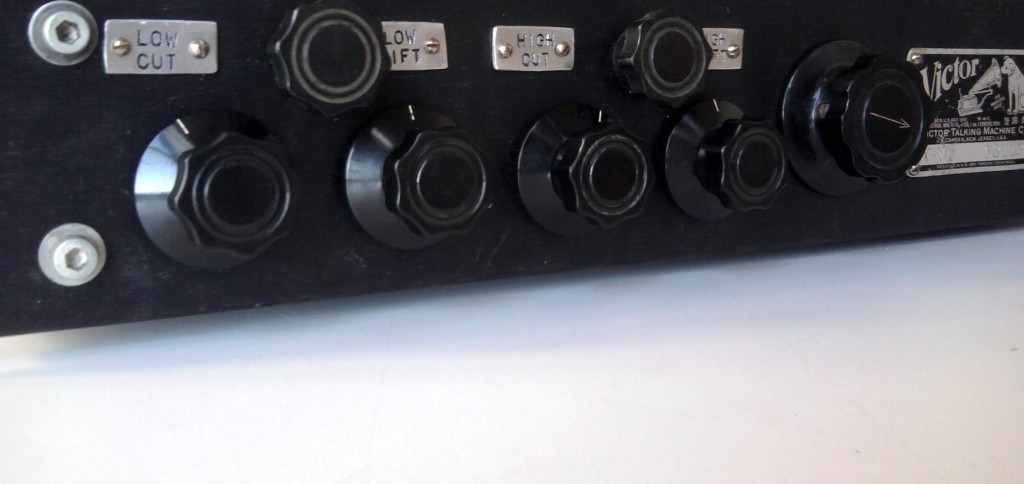 The vacuum-tube powered program EQ that I described in this previous post is nearly complete. This thing has sat on the shelf for a while, as it was a little daunting dealing with all those parts inside a 17x4x3 chassis. So far so good, though… very excited to fire this thing up in a session.
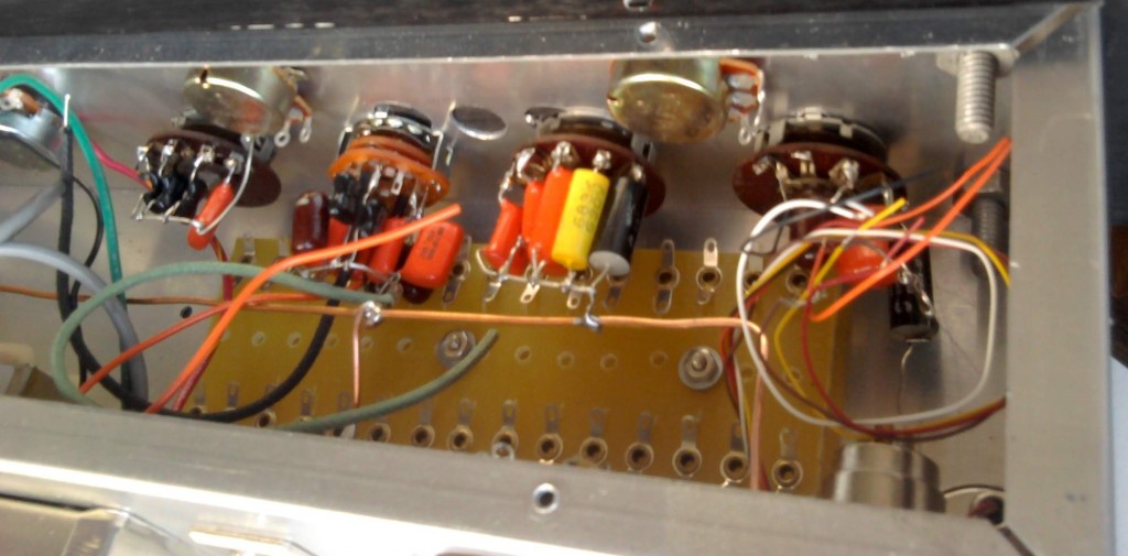 Here you can see the frequency-selection switches all wired up. The switches are 5-way, single-deck switches with the exception of the hi cut, which requires a 2-gang switch. The EQ has separate boost and cut sections, like a pultec, with 5 selectable frequencies for each. The amount of boost shelving is variable via a pot, while the attenuation controls are fixed cut. It would be easy to make the cut controls variable as well, but as you can see I am a little short on space! I suppose I should use a 3U enclosure the next time. Alright stay tuned…
UPDATE: This piece was finished, and it sold to a prominent producer/engineer before I had the chance to record a thorough demo of it. It worked out very well. The circuit performed as-advertised, and the only problem was that it had a little too much gain – enough to use a mic preamp in the majority of situations. Since it has sold it’s been used on several major records; when these albums are released I will provide links to some of the sounds tracked through it.
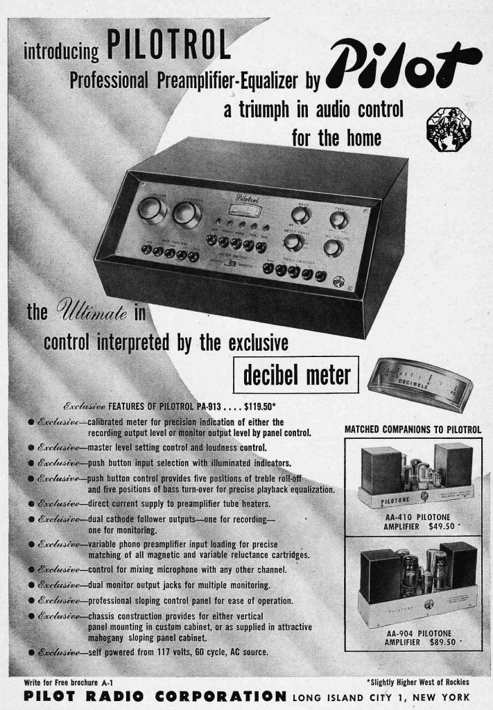 Pilot was one of the classic NYC Golden-Age Hi-Fi makers (see here for earlier coverage on PS dot com). Although the Pilotuner mono FM tuner series was their most iconic product, the Pilotrol was their flagship offering.
The Pilotrol seems like an attempt to satisfy the most compulsive hi-fi fans; it really seems like they tried to cram as many lights, buttons, features, and knobs in there as possible. What with the excess of buttons, slant-front cabinet, and VU meter, Pilot seems to have been trying to turn the simple act of using your audio system into an experience; I see shades of ‘Mission Control,’ ‘The Cockpit,’ and maybe police radio as well in the design. Anyhow, it’s too bad this is a mono unit; otherwise I’d be looking for one…
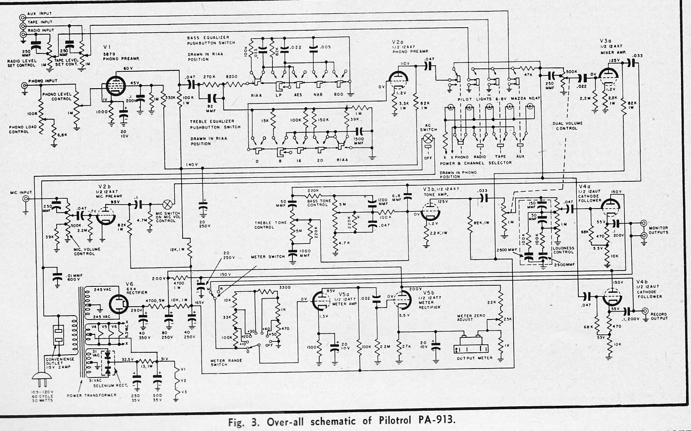 Here’s the schematic. Nice pentode phono input. Anyhow, we can see echos of the Pilotrol and its feature-laden ilk in much hi-fi gear of the 70s – consider a typical high-end receiver of that era. Modern equivalents offer even more features, but nowadays the buttons and lights have been replaced with menus and screens. In opposition to this thread, we have the minimalist streak best exemplified by Apple and its associates. Which operating principle do you prefer? Do you want the equipment to be in the background or the foreground of your audio-listening experience? Exactly what is ‘the experience’ for you? Hearing the sounds? Or is the operation of the apparatus essential to your enjoyment? At what point will technology become so advanced and so pervasive that ‘controls’ themselves can only been seen as quaint and nostalgic? Are we there yet?
See this link for some more thoughts on the function of ‘control’ in consumer audio equipment.
The RCA OP-6 ‘Portable Amplifier’ is one of a handful of truly visually-iconic vintage mic preamps. The OP-6 was designed as a “remote,” as-in, ‘on-location’ single-channel mic preamp for radio station broadcasts. It uses three 1620 (6J7) tubes – most mic pre designs of the period use two. Furthermore, the 1620s are in pentode operation rather than triode. The result: a ton of gain. 95db, apparently. This is almost twice as much gain as the classic RCA BA1 and BA2 mic pres. OP-6s are in high demand – click here for a seller asking $2900. Further indication: Blackbird Rentals in Nashville has thirteen in stock as rental units. The first time I heard an OP-6 in use was at Blackbird; I was producing/directing a live-in-the-studio performance for Martina McBride and John McBride was engineering; he was using the OP-6 for something… I can’t remember what exactly. Anyway, it caught my eye and we talked about it a bit; later I learned that he has an especially strong appreciation for these units. A strong endorsement coming from the man who likely owns more vintage pro audio gear than anyone who ever has or ever will live.
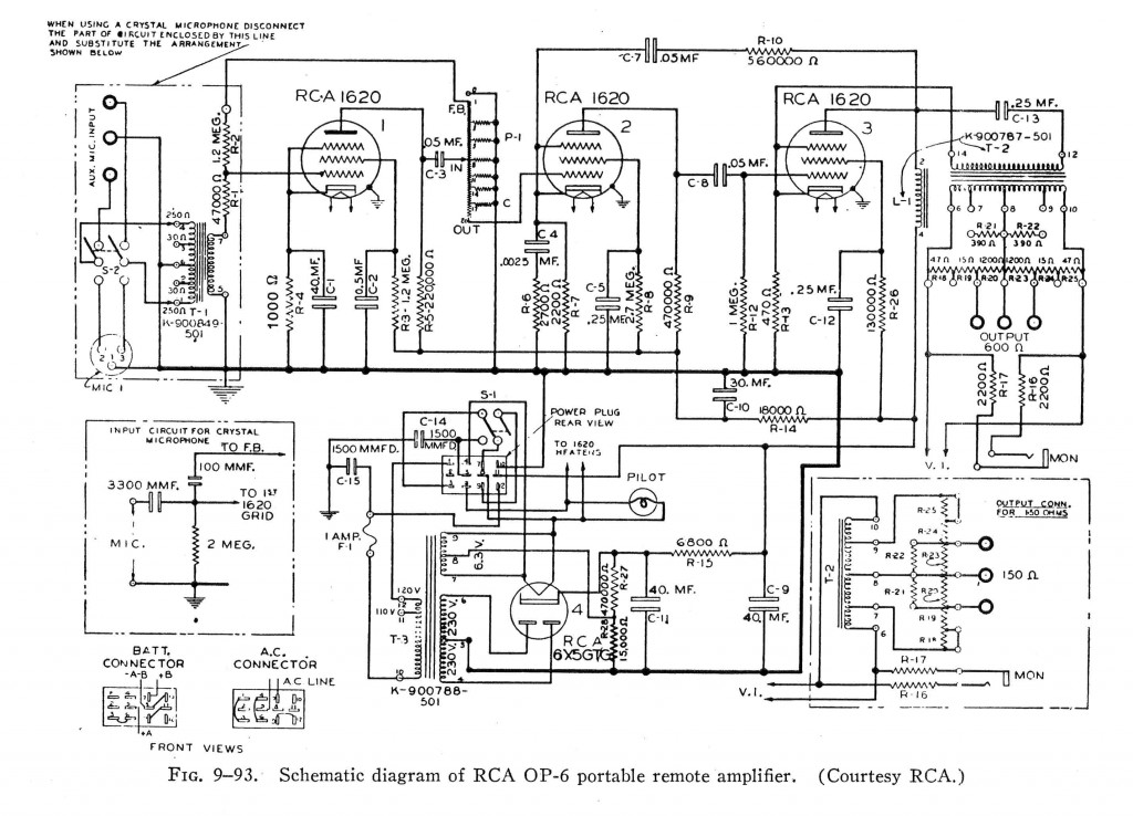 The OP-6 schematic is pictured above (this file is readily available in high-res on the internet). So anyhow, if we consider how in-demand the OP-6 is, it seems striking that no one offers a modern equivalent for sale, even on a small-scale level. If you take a close look at the circuit, the reasons become apparent. There are two big obstacles to re-creating even a semblance of an OP-6. First is the input attenuator:
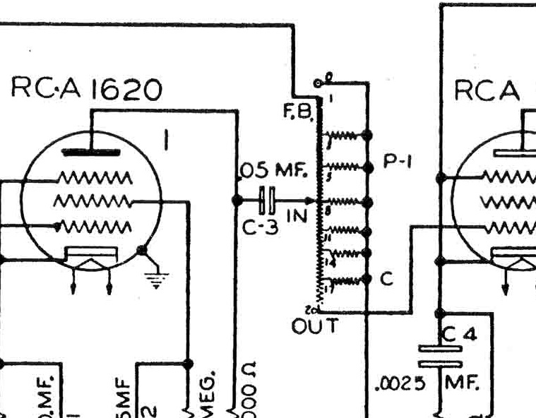 Sure, it’s a voltage divider; probably constant impedance; but what exactly are the values? And what about that value of that feedback path issuing from the attenuator back to the input stage? If I could get my hands on an original OP-6 and open up the attenuator, sure I could maybe sort it out. But I imagine that re-creating that part on custom order could cost hundreds of dollars; frankly I have no idea.
The second obstacle to re-creating the OP-6 is the output stage choke.
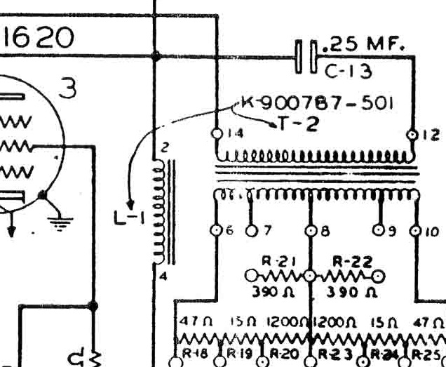 The choke is designated L-1 in the schematic. Curiously enough, it’s actually physically part of the output transformer. Based on this fact, there is zero chance that this was an off-the-shelf choke, say a UTC for example, that we could track down. OK – but the crucial value of a choke in a circuit like this is the inductance. So long as the voltage an current handling values are sufficient, any choke of same inductance should give a similar result. Now again, if I had an original OP-6, I could measure the inductance and maybe a current off-the-shelf part exists to satisfy the requirements. But… I don’t think anyone out there is gonna send me their prized OP-6 to open up. And $2900 is a pretty stiff R+D cost. So what do we do? Well, in the absence of any actual electrical engineering training, I looked for some good advice and then I guessed.
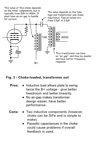 The very friendly+talented John Atwood sent me the diagram above; in response to what I can’t recall. This diagram explains why the choke is necessary in order to get the best possible performance from a single-ended vacuum tube line output stage. Looks pretty similar to our OP-6 output stage, right? Based on this… I made a wild guess. I ordered the very inexpensive Hammond 156C choke. 150mh inductance with 8ma current capacity. 8ma might be a little low, but I have found that Hammond really undersells the specs of their transformers, so I’m not worried.
Alright so now we’ve got a choke that might work. What about that input attenuator? The best course of action would probably be to get a used 100k Daven T-pad, but without implementing the feedback path that the stock OP-6 attenuator has, it seems like this is slightly pointless vis-a-vis maintaining originality. So instead: I used the input stage from my favorite, yes yet again, the RCA BA-2.
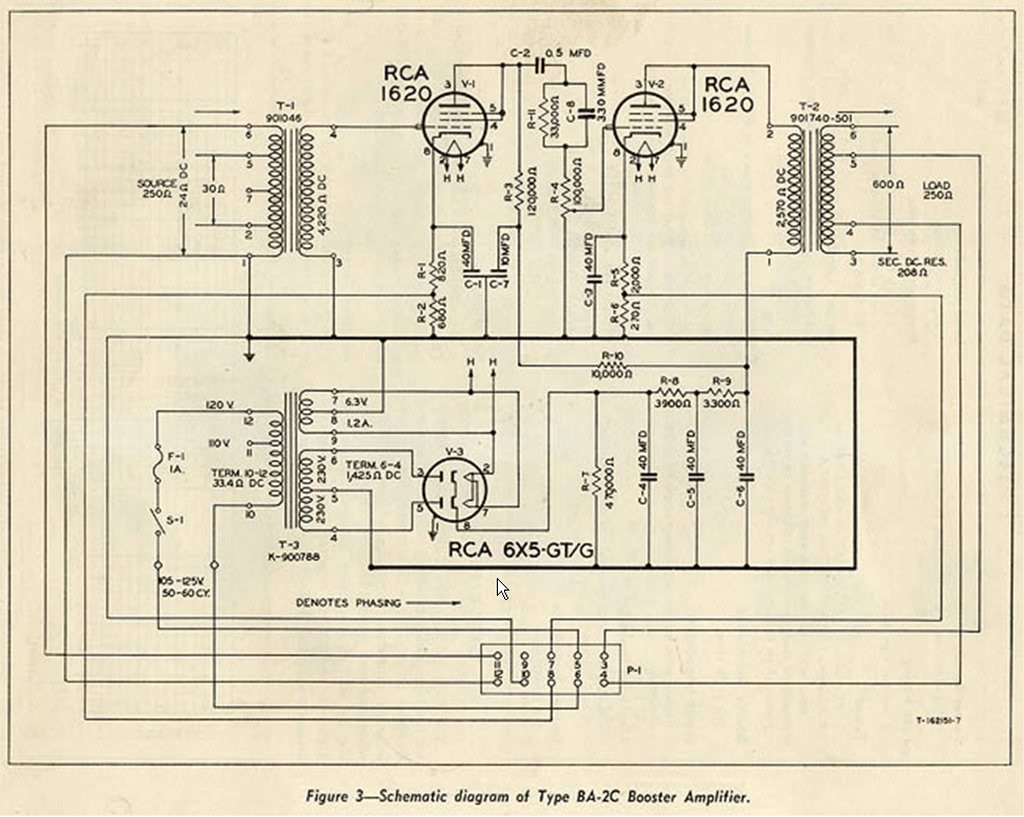 The BA-2 schematic is pictured above. The input stage uses a 1620 tube, wired as a triode, with a 100k ohm pot following it. So I just took this input stage, up to the pot output, and wired it in front of the second two OP-6 stages (starting at the grid of stage #2). When I did this, the whole system worked fine except when the volume pot was a zero (IE., when the grid of tube #2 is shorted to ground). This caused weird noise and a little humming. Not sure if this is due to the negative feedback in that stage, or if this is simply a general characteristic of 1620s when they are run in pentode – but it sounded awful. The easy solution? I added a 1M resistor from the grid to ground, and isolated this from the pot with a 1K grid-stopper resistor. Done and done. The BA2/OP6 Hybrid is born.
*************
********
***

 The finished piece is shown above. I used a 6X5 rectifier tube like the OP-6 uses; in fact, with the exception of using DC filament voltage, I kept the power supply the same as the OP-6.
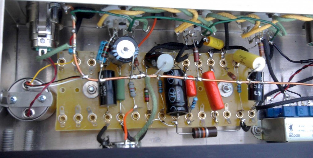 The audio portion of the circuit is shown above. What with the three pentode stages and feedback paths, this is extremely complicated for a mic preamp. A lot of parts. On the left you can see my usual Jensen 115 input transformer. Audio caps are a mix of Solen, sprague, and some random Russian ones. Basically whatever would fit. Resistors are random as well; now that I have confirmed that the piece works well, I will probably replace the carbon-comp resistors in the B+ chain with some quieter modern resistors. On the right is the output transformer. I used an edcor 15K: 600; $10.22!
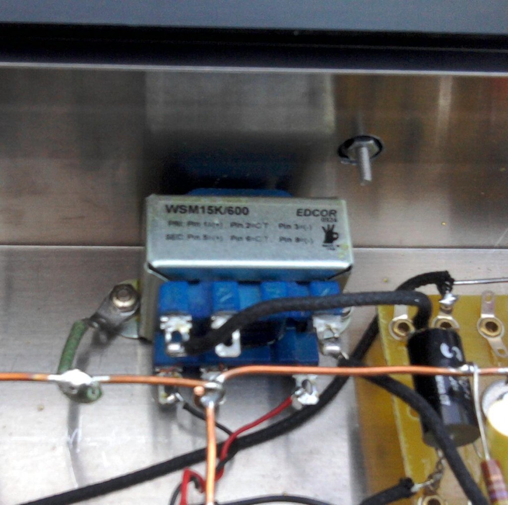 Even though this edcor is unshielded, there is zero hum following the volume pot. And as for performance? I did a frequency sweep through the entire unit; response is absolutely flat from 15hz to 10k hz. At 10k there is a rise of about 1db up to 22khz, at which point response begins to fall of pretty rapidly. This is really excellent performance considering the inexpensive transformers. I did not measure the gain but there is a lot of. The output level can get extremely hot.
Anyhow. That’s it for now. As soon as I have a minute I will provide some audio test examples; I’ll post some A/B examples of this unit versus an API 512, hopefully with both acoustic gtr and drums.
Thanks to DW at EMRR for helpful suggestions regarding this project.
***UPDATE*** Listening test has been done and results are posted here.
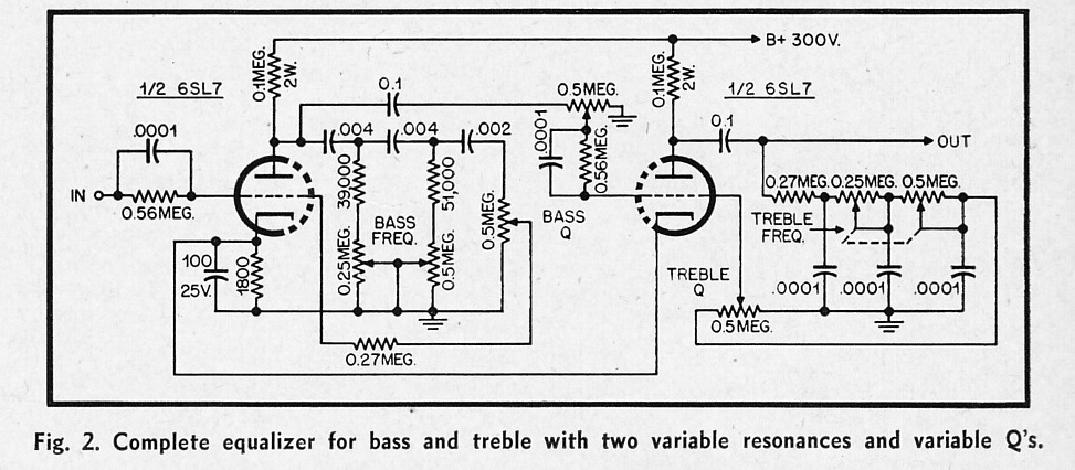 Circuit for a simple bass/treble parametric equalizer that uses no inductors. Could be a useful piece. Not sure if 250k/500k dual pots are still available? Since I have still not finished building the last tube EQ project that I described, so I’m not likely to craft this thing anytime soon. If anyone out there picks this up and builds one, LMK…
Going back to AUDIO magazine in the early 50s: a few circuits that caught my eye. As always, if any of y’all out there build any of these, drop us a line and let us know how it went.
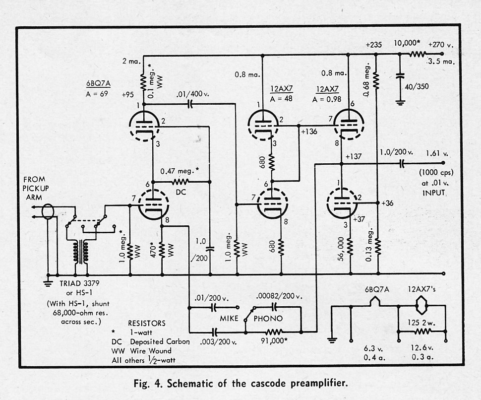 A ‘cascode’ preamp which features very high gain and defeatable compensation for phono cartridge. I am not aware of any available mic preamp that uses this circuit. a lot of gain available here…
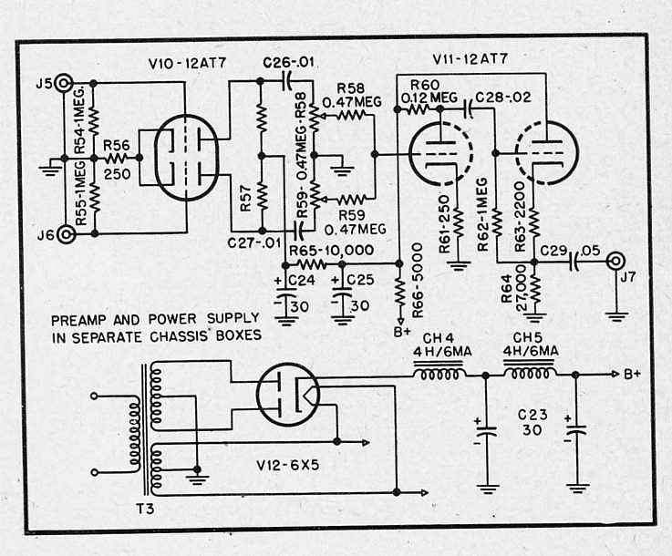 A low-gain preamp that mixes two high-impedance signals to a medium-impedance output. Add a few transformers (500: 50K inputs, 15k:600 output) and this could be a useful tool for selecting/blending two mic signals to one track of (tape). IE put a couple of mics on a gtr amp, blend to taste… I generally do this using submasters (busses) on the console but here’s a potential way to do it that uses a much simpler signal path, IE right from the mics into the convertor (or tape machine).
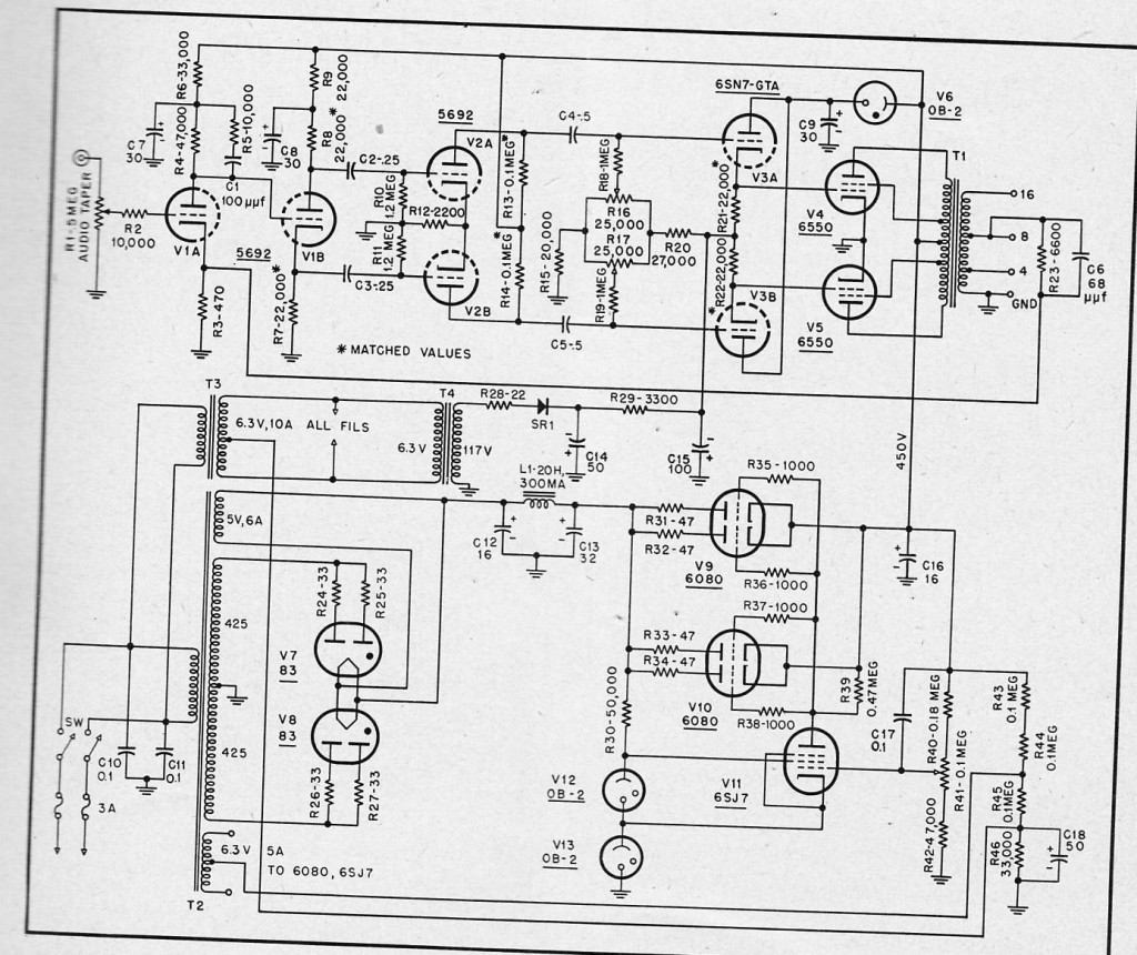 A 50-watt ultralinear power amp using 6550 power tubes
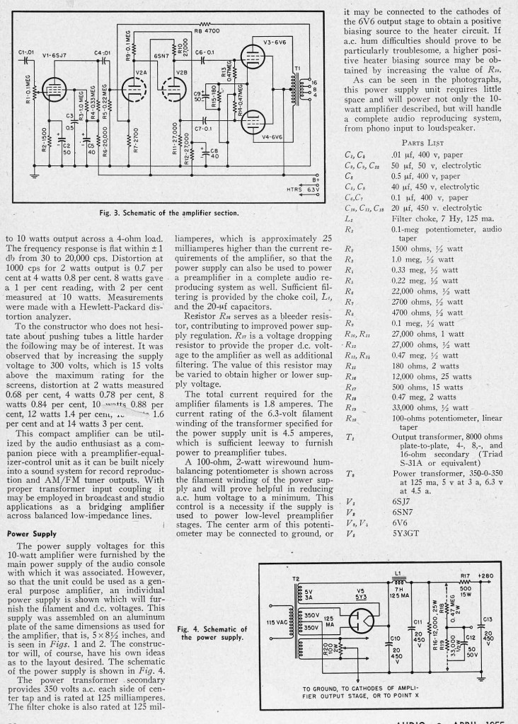 A 12-watt 6V6 power amp with some negative feedback and a pentode input stage.
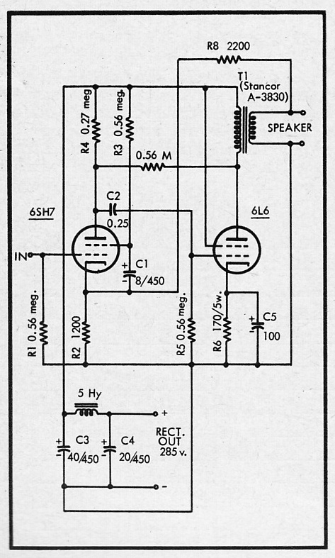 A simple 8-watt power amp that uses a 6SH7 input tube and a single 6L6 output. This circuit uses a great deal of negative feedback in order to supposedly get more linear response with cheap output transformers. I’ve never used the 6SH7 tube before… curious though.
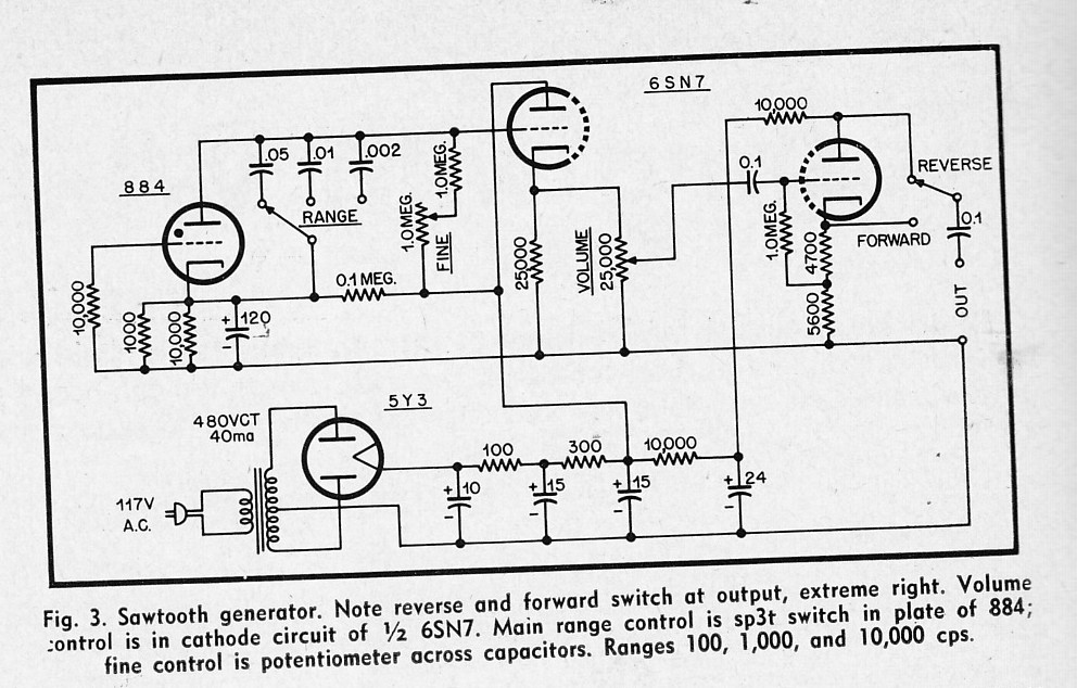 A simple design for a variable sawtooth wave generator.
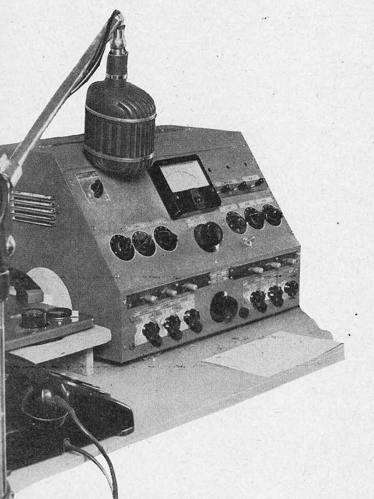 Some more interesting bits from AUDIO magazine c 1955: plans and schematics for a radio station mixing console. Very little in terms of equalization devices, and no compressors discussed, but a wealth of ideas for low-level and line-line level amplifiers and mixing circuits. Download the entire piece as a 4-page PDF:
DOWNLOAD: DIY_Console_1955
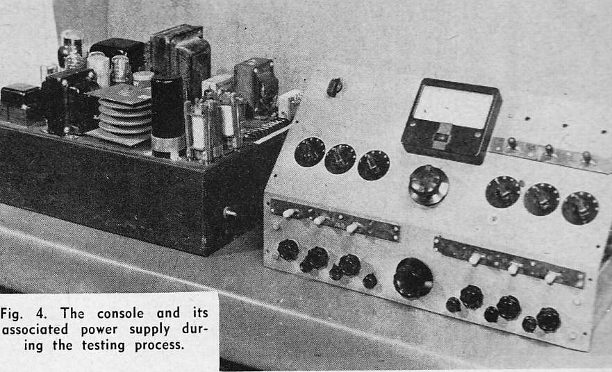 There is little of real interest here in terms of a complete system, as the system discussed is a mono mixer; but if you are interested in some simple, novel mic preamp and line driver plans, you might find this worthwhile. Personally I am drawn to the OD-3 regulator tubes; i know zero about voltage regulation tubes; I have always used Zener diodes in the past when i needed regulated voltage; but the very simple way that these tubes are used here leads me to believe that they are pretty easy to work with.. Might wanna try them out. They are just $5.15 at AES.
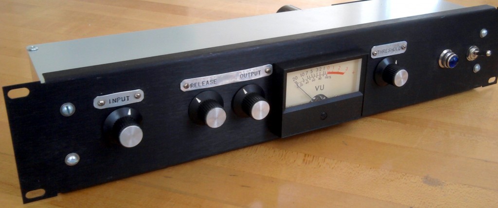 In a previous post, we looked at the Altec 436 vari-mu tube compressor. I built one of these a few years ago, and it never really got used all that much because the output level is so hot. The 436 is a very primitive compressor design, and it sounds awesome- but it was also built primarily for service is installed sound systems: industrial paging use, etc. The stock 436 circuit adds a lot of level to your signal if you have the input level set high enough to actually cause significant compression. I built an external attenuator box using a 600-ohm Daven T-pad attenuator and a UTC transformer to re-balance the signal, but this was not really an ideal solution. The box was pretty big and heavy and I generally could not be bothered with taking it out and setting it up.
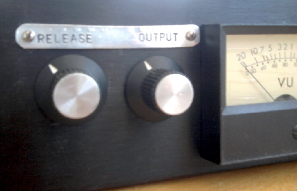 The solution came to me when I was examining the circuit of the Gates sta-level. Here’s the schematic if you want to take a look. Now, this may look a lot different than the Altec 436 schematic, but the differences are not too significant – other than the fact that the gates has a regulated power supply, the circuits function in the same way; the main difference is the particular types of tubes that are used. Both are fully-balanced vari-mu compressors which are staged as (input transfo)-(attenuator pot)-(vari mu input amp)-(driver stage in Gates only)-(output amp)-(output signal rectified, timed, and sent to grid of input stage to regulate input stage amplification)- (output transfo).
The Sta-level, however, has an output level control, whereas the Altc 436 does not. So how do they implement this?
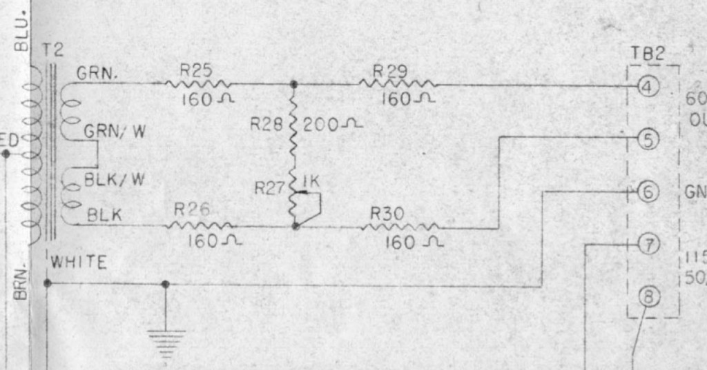 Pretty simply. 5 resistors and a normal linear taper pot give us an output loss that we can vary between 10 and 16db, while still maintaining a safe operating impedance. In all fairness: the BEST way to do this would be to use a balanced H-pad variable attenuator, which would give us the ability to vary the output from NO loss to, say 20db or so; but balanced H-attenuators are crazy expensive and very large physically; too large to fit inside an altec 436 chassis, certainly. Another option would be to use a variable T-pad after the output transformer, and then add an additional 600/600 transformer after the T-pad in order to re-balance the signal (there is a certain vintage vari-mu compressor that works this way, but i can’t seem to recall which; anyone?). This solution is also not ideal from a cost and size perspective, although it would certainly be less expensive than the balanced H attenuator.
Anyhow, the major downsides to the ‘Gates-solution’ are: 10db loss is inevitable; output impedance will vary slightly with use of control; variation range is limited to 6 db span. Well; i used my output modded 436 in a session yesterday, and for what its worth, here’s what I can tell you: the minimum 10db loss is welcome – it put the 436 into the same basic operating range as my 1176 and Distressor; the impedance mismatch (into a Lynx Aurora) did not cause any audible problems that i could detect when used on guitars and drum machines; and the 6db control range was fine as well – i was dialing in levels and getting sounds into Pro Tools with no fuss.
****
Before I drilled a fresh hole into the face of my 436 clone, I built the intended circuit into a tiny outboard box. When the design confirmed itself, I added the circuit into the 436 itself. But about this little test-circuit box: it’s lightweight enough that it can simply hang off the patchbay, supported by the patch cables themselves. Now every vintage mic preamp that I have can be given variable output control quickly and easily. This will allow me to dial in extra-gritty sounds using the preamp gain control (which is generally interstage rather than input or output), and then use this little device to get the level back down to an appropriate level to hit the convertor.
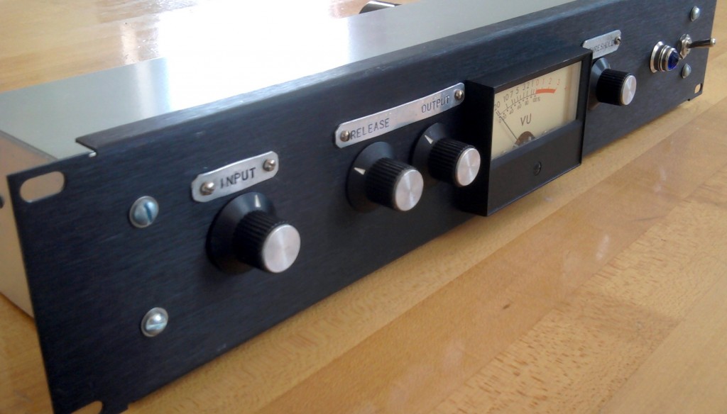 If you own a vintage Altec 436 or 438 and you find that you have to battle the high output level, I highly suggest that you give this modification a shot. It’s very easy to simply build it into an outboard project box at first in order to see how you like it before you drill a hole in yr Altec. And if you use any vintage tube gear in the studio: try making one of the little boxed-versions of the circuit. It will really open up some new creative and sonic possibilities for the gear you already have.
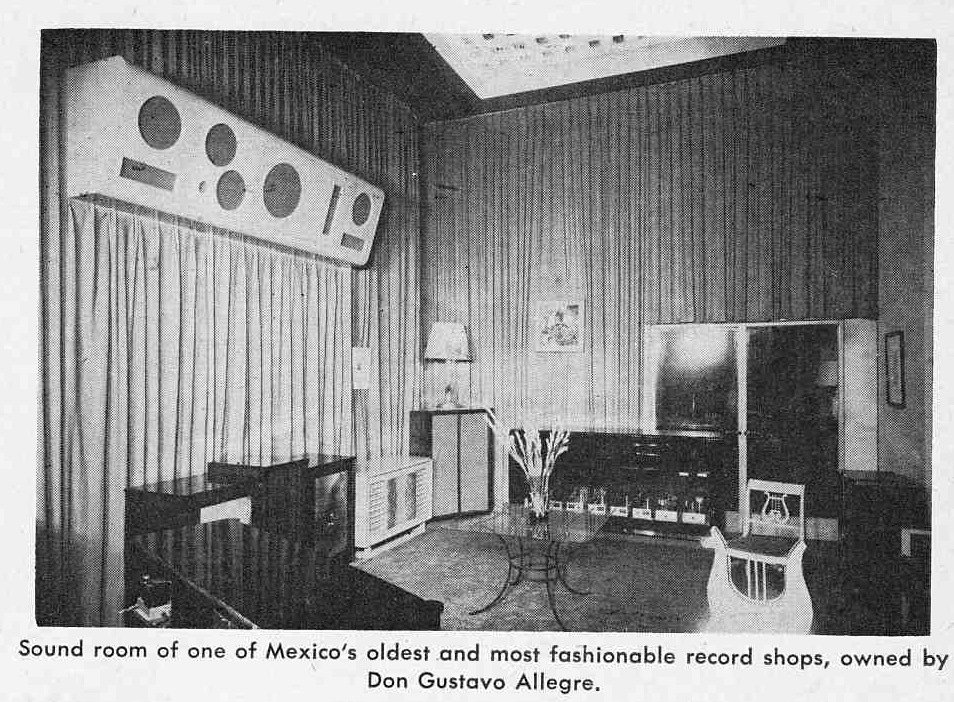 A two page article from AUDIO magazine circa 1955. Consider this article in comparison to “Japan Goes Hi Fi.” How differently these two countries have developed since these pieces were written. Both certainly became manufacturing powerhouses, but Mexico has been much less able to keep the profits from those operations in their country. I have owned plenty of audio-objects made in Mexico (Fender guitar amps come to mind) but I have personally never seen a Mexican hi-fi brand. Anyone? Also: please note: this article is presented for historical reference only; I do not endorse the political/ethnic generalizations and characterizations that author makes.
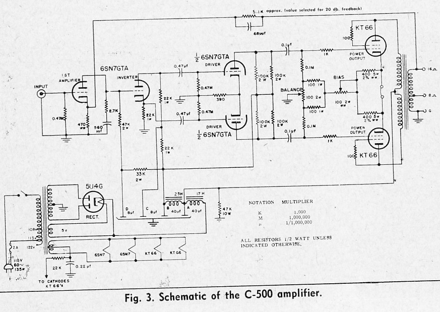 The Craftsmen C-500 power amplifier
Today we have some hi-fi amplifiers from the mid 1950s to look at. Many of them use unusual output transformers with split primaries, so I am really not sure if it’s even possible to build these designs today. The Craftsmen C-500 pictured above uses a standard PP-VC output transformer; it also uses readily available, robust 6SN7 and Kt66 (aka 6L6) tubes. Check out the circuit in the output cathode bias; even though this is a cathode-biased amp, there is a provision for adjusting the overall bias, as well as a balance adjustment ( to allow the use of unmatched power tubes). Here’s a few more…
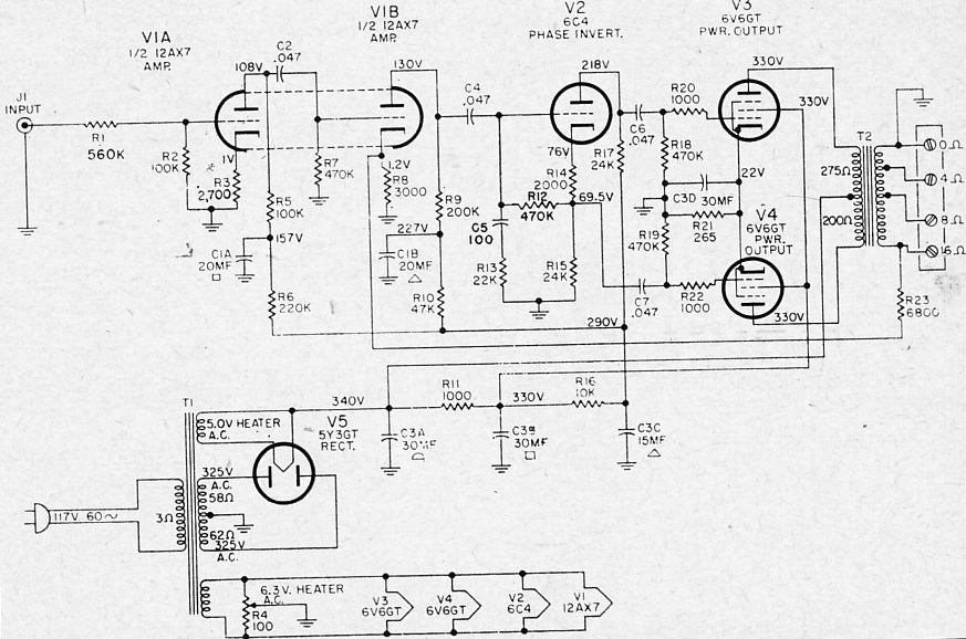 General Electric A1-300 power amp. This is a good simple design that will provide 12 watts.
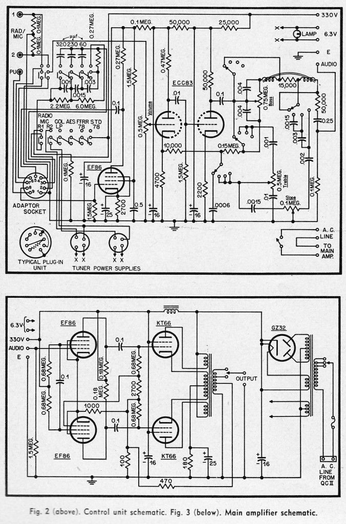 The Quad II pre-amp and power amp.
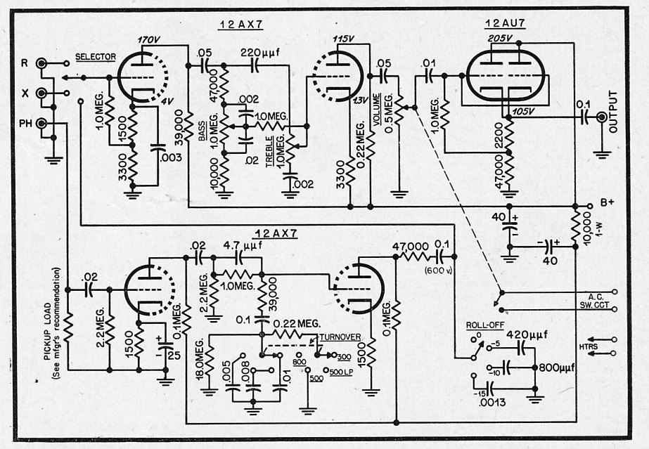 A DIY hi fi preamp design from 1954. Note the very sturdy parallel-cathode-follower output (the 12AU7 section). This could probably drive a 10K load pretty easily.